Image classification using range information
a technology of range information and image, applied in the field of digital image classification, can solve the problems of large frustration for many users, many images sitting unused, and it is difficult to distinguish between objects with similar attributes, and achieve the effect of improving accuracy
- Summary
- Abstract
- Description
- Claims
- Application Information
AI Technical Summary
Benefits of technology
Problems solved by technology
Method used
Image
Examples
first embodiment
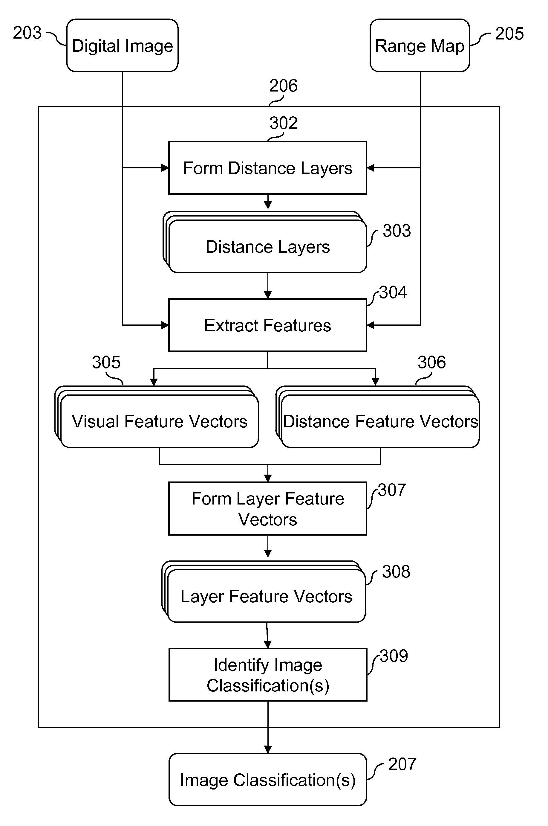
[0047]FIG. 4 is a flowchart illustrating additional details for the identify image classification(s) step 309 in FIG. 3, according to the present invention. In generate global feature vector step 402 the layer feature vectors 308 for each of the distance layers are concatenated together to form a single global feature vector 403. The global feature vector 403 is fed to a trained classifier in apply classifier step 404 to determine the one or more image classifier(s) 207. For example, if the global feature vector 403 contains a distance layer where the distance feature is “far” and where the visual features indicate that it is red in color and has a low amount of texture, the trained classifier would indicate a high likelihood that the digital image was a sunset scene. On the other hand, if the distance feature is “near” the distance layer would be more likely to correspond to a red object such as a shirt and the trained classifier would indicate a low likelihood that the image is a ...
second embodiment
[0048]FIG. 5 is a flowchart illustrating additional details for the identify image classification(s) step 309 in FIG. 3, according to the present invention. In this variation, individual classifiers are first applied to each distance layer to determine layer scores which are then fed into another classifier. The input to the identify image classification(s) step 309 is a layer feature vector 308, which is comprised of individual layer feature vectors 310 for each of the distance layers 303 (FIG. 3). Each of the individual layer feature vectors 310 is processed using a layer classifier step 502 to form layer score vectors 503. The layer classifier step 502 uses a classifier that has been trained to operate on individual layer feature vectors 310. The layer score vectors 503 are comprised of confidence-rated prediction scores giving a probability for each classification category. The score vectors from each of the distance layers are concatenated to form a combined score vector 505 in...
third embodiment
[0049]FIG. 6 is a flowchart illustrating additional details for the identify image classification(s) step 309 in FIG. 3, according to the present invention. In this variation, individual classifiers are first applied to each distance layer to determine predictions of the most probable classification, which are then fed into another classifier. The input to the identify image classification(s) step 309 is a layer feature vector 308, which is comprised of individual layer feature vectors 310 for each of the distance layers 303 (FIG. 3). As in the method shown in FIG. 5, each of the individual layer feature vectors 310 is processed using a layer classifier step 502. In this case, the output of the layer classifier step 502 is a layer prediction 603, which is an indication of the most probable image classification given the layer feature vector 310 for that particular distance layer. The layer predictions 603 for the individual distance layers are combined to form a combined prediction ...
PUM
 Abstract
Description
Claims
Application Information
 - R&D
- Intellectual Property
- Life Sciences
- Materials
- Tech Scout
- Unparalleled Data Quality
- Higher Quality Content
- 60% Fewer Hallucinations
Browse by: Latest US Patents, China's latest patents, Technical Efficacy Thesaurus, Application Domain, Technology Topic, Popular Technical Reports.
© 2025 PatSnap. All rights reserved.Legal|Privacy policy|Modern Slavery Act Transparency Statement|Sitemap|About US| Contact US: help@patsnap.com


