
Asynchronous combustion system

a combustion system and synchronous technology, applied in the direction of machines/engines, efficient propulsion technologies, lighting and heating apparatus, etc., can solve the problem of increasing pressure within the limited volume of the combustion chamber

Inactive Publication Date: 2012-09-18
BAKER MARK
View PDF26 Cites 5 Cited by
  • Summary
  • Abstract
  • Description
  • Claims
  • Application Information

AI Technical Summary

Benefits of technology

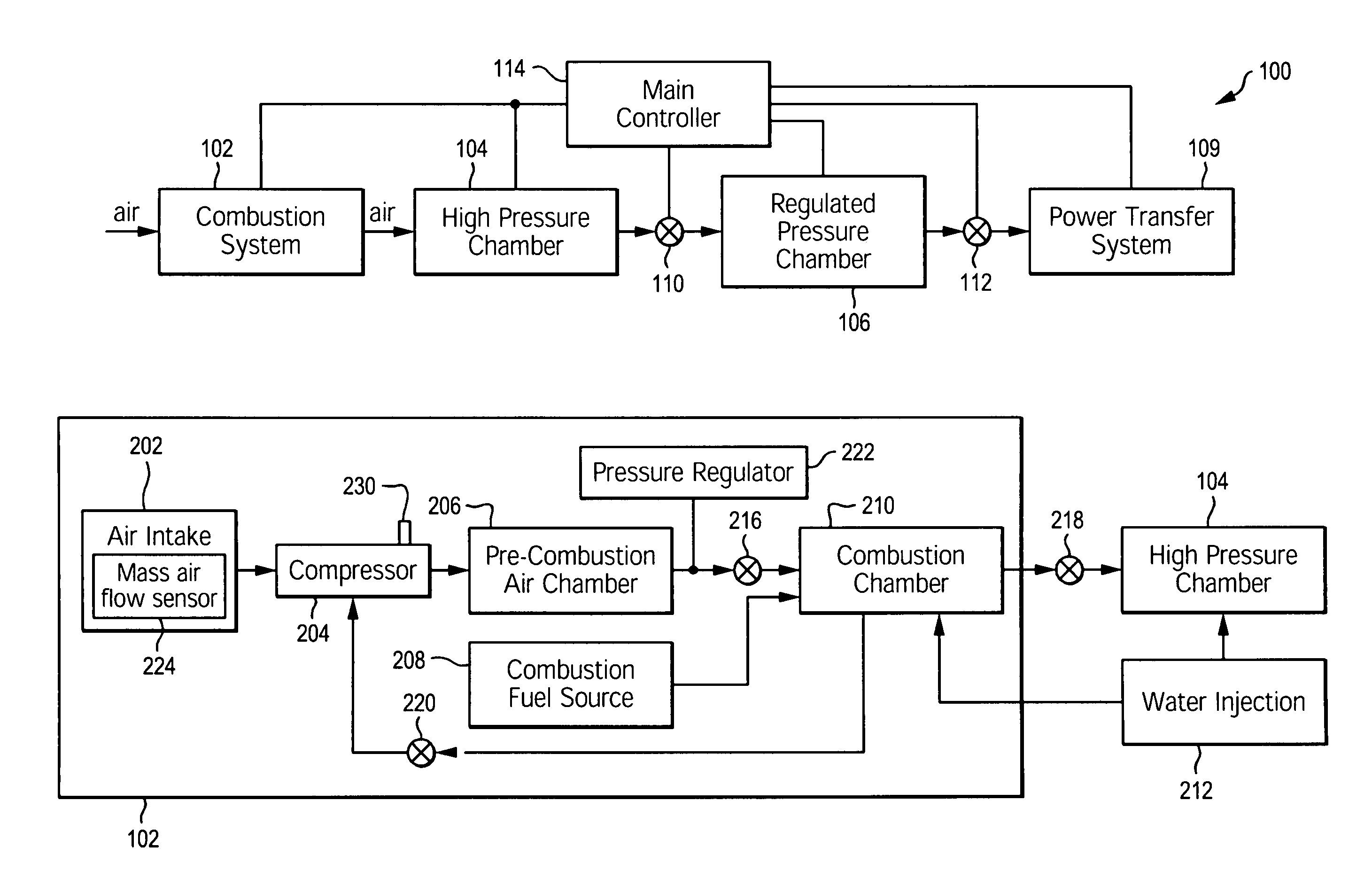
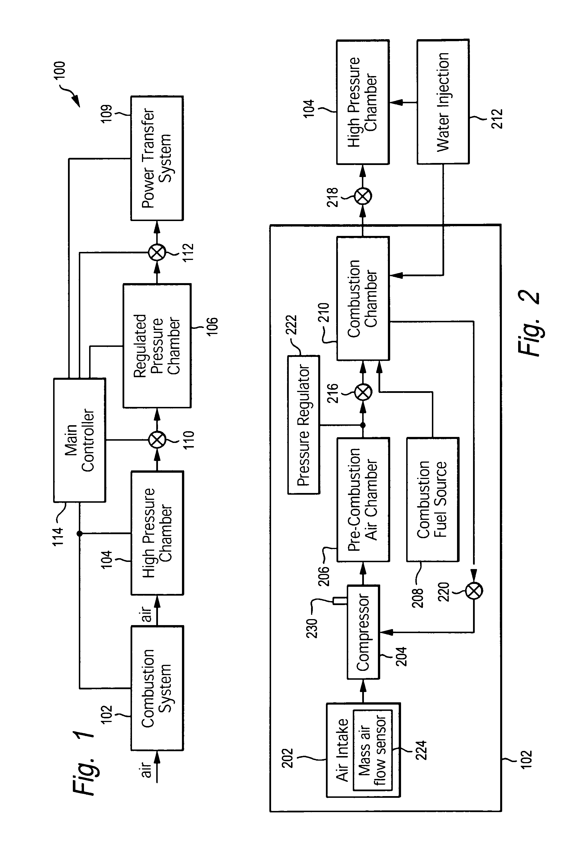
[0006]An asynchronous combustion system (ACS) and method of use improves the efficiency of internal combustion engines by supplying high-pressure gas to a power transfer system. The ACS is an external combustion system that utilizes the heat energy typical lost in internal combustion engines such as four cycle, two cycle, turbine, and rotary engines.
[0007]More specifically, the ACS converts the high temperature produced by combustion into a fluid volume of high pressure gas without requiring a boiler or heat exchanger. By injecting a fluid directly into a combustion system, heat energy that may otherwise be wasted is converted directly into high pressure gas. The conversion of the liquid into a gas is a high volumetric expansion ratio and follows the ideal gas law V=nRT / P. Because the ACS is an external combustion system, the combustion process can be controlled, without dependence on the operating conditions of the machine utilizing the ACS.
[0011]The main controller also controls a first valve wherein the first valve allows the high pressure gas contained in the pre-combustion air chamber to flow into the combustion chamber. The fuel flow into the combustion chamber is also controlled by the main controller. Because the compressed air is admitted into the combustion chamber through the first valve, in contrast to a four stroke and rotary engine, the combustion chamber does not perform the compression function and therefore, oil contamination is reduced.
[0014]The large capacity of the high pressure hot gas stored in the high pressure chamber is used to supply the high pressure gas contained in the regulated pressure chamber. The high pressure gas from the regulated pressure chamber is supplied to the power transfer system. The amount of high pressure gas supplied to the power transfer system is determined by the needs of the power transfer system and conditions such as acceleration or deceleration. The conversion of heat energy into pressure energy reduces the need for a cooling system.

Problems solved by technology

The leftover hot gases produced by this combustion tend to occupy a far greater volume than the original fuel, thus creating an increase in pressure within the limited volume of the combustion chamber.

Method used


Image

  • Asynchronous combustion system
  • Asynchronous combustion system
  • Asynchronous combustion system

Examples


Embodiment Construction

[0025]In the following detailed description, reference is made to the accompanying drawings that form a part hereof, and in which is shown by way of illustration, specific embodiments in which the invention may be practiced. These embodiments are described in sufficient detail to enable those skilled in the art to practice the invention, and it is to be understood that other embodiments may be utilized. It is also to be understood that structural, procedural and system changes may be made without departing from the spirit and scope of the present invention. The following detailed description is, therefore, not to be taken in a limiting sense, and the scope of the present invention is defined by the appended claims and their equivalents. For clarity of exposition, like features shown in the accompanying drawings are indicated with like reference numerals and similar features as shown in alternate embodiments in the drawings are indicated with similar reference numerals.

[0026]Referrin...


PUM


Abstract

A device and method that converts the high temperature produced by combustion into a fluid volume of high pressure gas without requiring a boiler or heat exchanger. By injecting a fluid directly into a combustion system, heat energy that may otherwise be wasted is converted directly into high pressure gas.

Description

BACKGROUND OF THE INVENTION[0001]1. Technical Field[0002]This invention relates to internal combustion engines, and more particularly, to the combustion of an internal combustion engine.[0003]2. Description of Related Art[0004]In a typical combustion engine, fuel and air are mixed in a combustion chamber and the fuel and air mixture is combusted. The leftover hot gases produced by this combustion tend to occupy a far greater volume than the original fuel, thus creating an increase in pressure within the limited volume of the combustion chamber. The pressure can be used to do work, for example, to move a piston on a crankshaft or rotate the blades of a turbine. The energy can be converted to various types of motion or to produce thrust when directed out of a nozzle as in a rocket or jet engine.[0005]For example, a reciprocating engine, also known as a piston engine, is a heat engine that uses one or more pistons to convert pressure into a rotating motion. There may be one or more pis...

Claims


Application Information

Patent Timeline
IPC IPC(8): F02C5/00F02C7/00F02G1/00F02G3/00
CPCF23L7/002F23R3/005F23R3/04F23R3/26Y02T50/675Y02T50/60
Inventor BAKER, MARK
Owner BAKER MARK
Learn More