
Vehicle-use collision mitigation apparatus

a technology for collision mitigation and vehicle use, which is applied in the direction of pedestrian/occupant safety arrangement, using reradiation, instruments, etc., can solve the problems of vehicle not being able to reduce much, vehicle tends to decelerate abruptly, and braking force is generated, so as to mitigate the shock of collision

Active Publication Date: 2012-09-04
DENSO CORP
View PDF45 Cites 18 Cited by
  • Summary
  • Abstract
  • Description
  • Claims
  • Application Information

AI Technical Summary

Benefits of technology

[0016]According to the present invention, it becomes possible to avoid, or at least mitigate the shock of collision between a vehicle provided with the brake assist control function and the automatic brake control function, and a vehicle following this vehicle.

Problems solved by technology

When such a brake assist control function operates, the vehicle tends to decelerate abruptly, because the braking force generated by the braking operation by the driver is increased.
Accordingly, in the case of the vehicles provided with the brake assist control function, the possibility of avoiding collision with the following vehicle cannot be lowered much by giving an alarm to the following vehicle at the same time of performing the pumping braking operation.

Method used


Image

  • Vehicle-use collision mitigation apparatus
  • Vehicle-use collision mitigation apparatus
  • Vehicle-use collision mitigation apparatus

Examples


Embodiment Construction

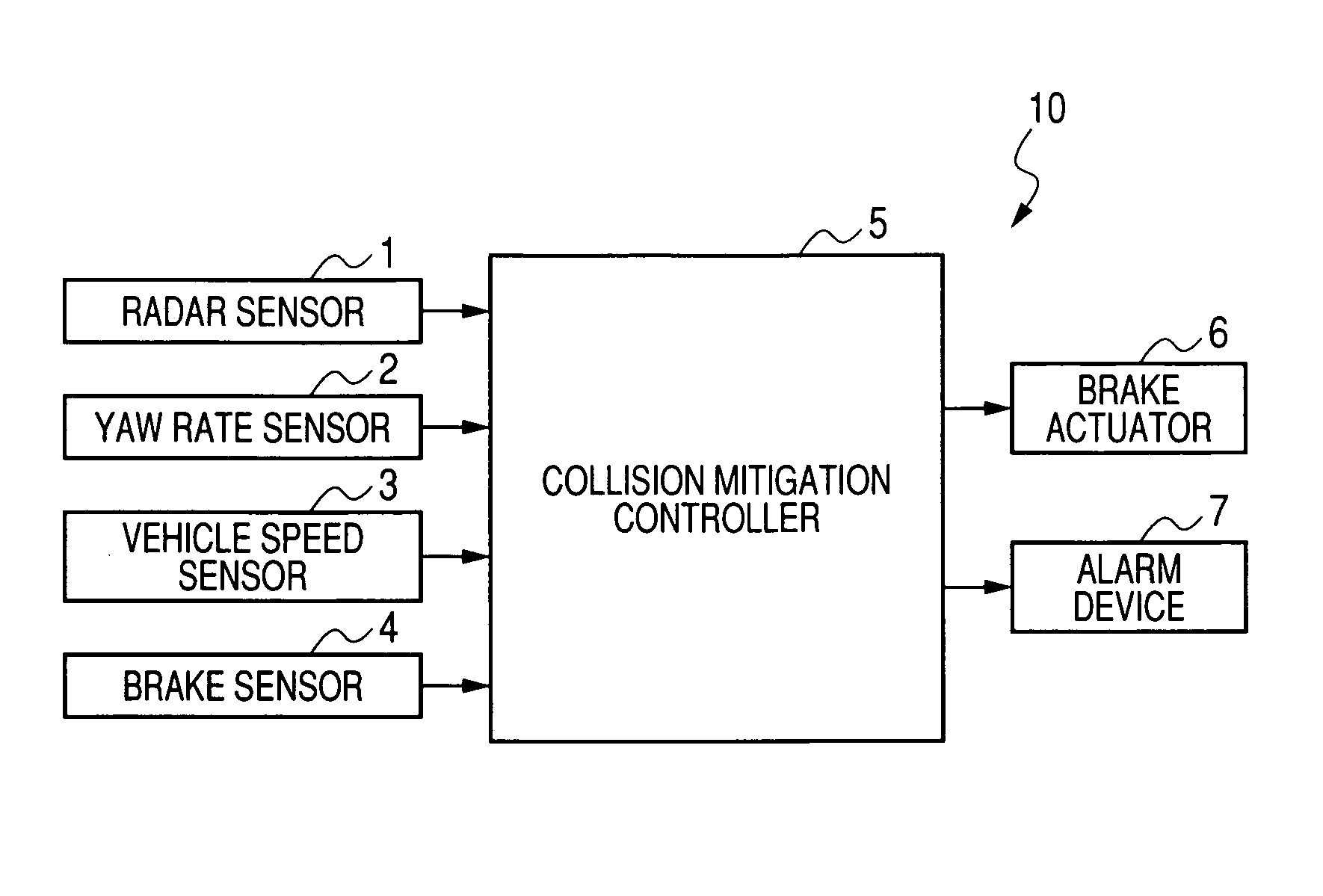
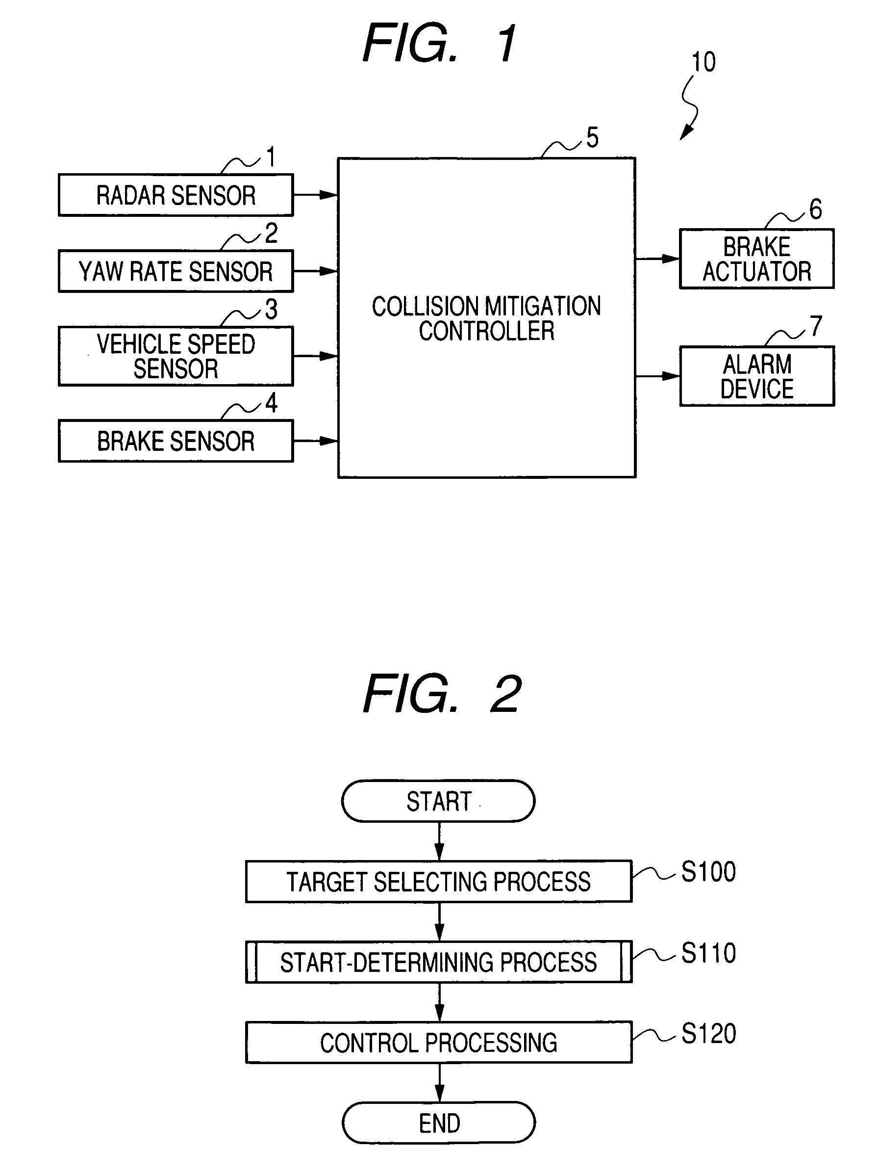
[0022]FIG. 1 is a block diagram showing an overall structure of a vehicle-use collision mitigation apparatus 10 according to an embodiment of the invention.

[0023]As shown in FIG. 1, the collision mitigation apparatus 10 includes various sensors to obtain information used to determine whether or not there is a risk of collision between the vehicle on which the vehicle-use collision mitigation apparatus 10 is mounted and a forward obstacle such as a preceding vehicle. More specifically, the collision mitigation apparatus 10 includes a radar sensor 1, a yaw rate sensor 2, a vehicle speed sensor 3, and a brake sensor 4.

[0024]The radar sensor 1 may be a laser radar sensor configured to emit a laser beam so as to scan a predetermined angular range ahead of the vehicle, in order to detect a distance and direction to a forward obstacle on the basis of the laser beam reflected from the forward obstacle and received by the laser radar sensor. Also, the radar sensor 1 may be a millimeter wave ...


PUM


Abstract

The vehicle-use collision mitigation apparatus includes a function of calculating a TTC indicative of a time remaining before collision with a forward obstacle on the basis of the distance to this obstacle and the reference speed therebetween, a function of alarming a driver of the vehicle of presence of a risk of collision with the obstacle if the TTC is shorter than a predetermined first time, a function of increasing a braking force generated by a braking operation performed by the driver if the TTC is shorter than a predetermined second time not longer than the predetermined first time, and a function of automatically generating a braking force if the TTC is shorter than a predetermined third time shorter than the predetermined first time. The alarming function is configured to make an alarm for a driver of a following vehicle that the preceding vehicle may decelerate abruptly.

Description

CROSS-REFERENCE TO RELATED APPLICATION[0001]This application is related to Japanese Patent Application No. 2007-156819 filed on Jun. 13, 2007 the contents of which are hereby incorporated by reference.BACKGROUND OF THE INVENTION[0002]1. Field of the Invention[0003]The present invention relates to a vehicle-use collision mitigation apparatus configured to execute a brake assist control to increase a braking force generated by a braking operation of a driver of a vehicle, and automatically generating a braking force if the driver does not perform any braking operation when there is a risk of collision with a forward obstacle.[0004]2. Description of Related Art[0005]There is known a vehicle-use collision avoidance apparatus having an automatic brake control circuit configured to automatically perform a braking operation if there is a high risk of collision with an obstacle. For example, refer to Japanese Patent Application Laid-open No. 4-362452. This automatic brake control circuit au...

Claims


Application Information

Patent Timeline
Patent Type & Authority Patents(United States)
IPC IPC(8): B60W30/08B60R21/00B60T7/12B60T8/00
CPCB60T7/22B60T2201/024
Inventor NODA, KAZUHIROITO, YOSUKEHASHIMOTO, KAZUMAISOGAI, AKIRA
Owner DENSO CORP
Learn More