Passive anti-collision damping multi-rotor drone

A multi-rotor unmanned aerial vehicle and anti-collision technology, which is applied in the field of unmanned aerial vehicles, can solve the problems of inability to adjust, low position probability, affecting flight, etc., and achieves the effects of simple setting, flight safety, and simple structure

Active Publication Date: 2019-03-26
SOUTHWEST JIAOTONG UNIV
View PDF7 Cites 3 Cited by
  • Summary
  • Abstract
  • Description
  • Claims
  • Application Information

AI Technical Summary

Problems solved by technology

[0007] (3) The price of sensors used in active collision avoidance is often relatively high
When a collision occurs, the angle of rotation is uncertain and can be large or small, so the probability of just turning to the limit position is low
[0014] 2. The drone is unbalanced during the relative horizontal rotation
When a collision occurs at a certain place, the inner and outer anti-collision bars at this place will rotate relatively horizontally, while the positions of the anti-collision bars at other positions will not change. balance
[0015] 3. The attitude of the UAV after the collision was not adjusted, but the effect of the collision was transferred through the anti-collision bar, but the effect on the UAV after the collision was not adjusted
Added an additional process when installing the protection device, and brought new loads to the drone
[0020] 2. The top protection cross net is easily disturbed by small objects such as branches when encountering tree branches, which will affect the flight
[0021] 3. The setting of the protection device is more complicated, such as the connection of various threads, the installation of the protection rod and the connection of the protection line
[0022] 4. The protection device can only slow down the effect of collision and prolong the time for processing the collision effect, but it cannot adjust the effect on the UAV after the collision, that is, it cannot adjust the posture of the UAV to make it balanced

Method used


Image

  • Passive anti-collision damping multi-rotor drone
  • Passive anti-collision damping multi-rotor drone
  • Passive anti-collision damping multi-rotor drone

Examples


Embodiment Construction

[0054] In the accompanying drawings, the meanings of each number are as follows:

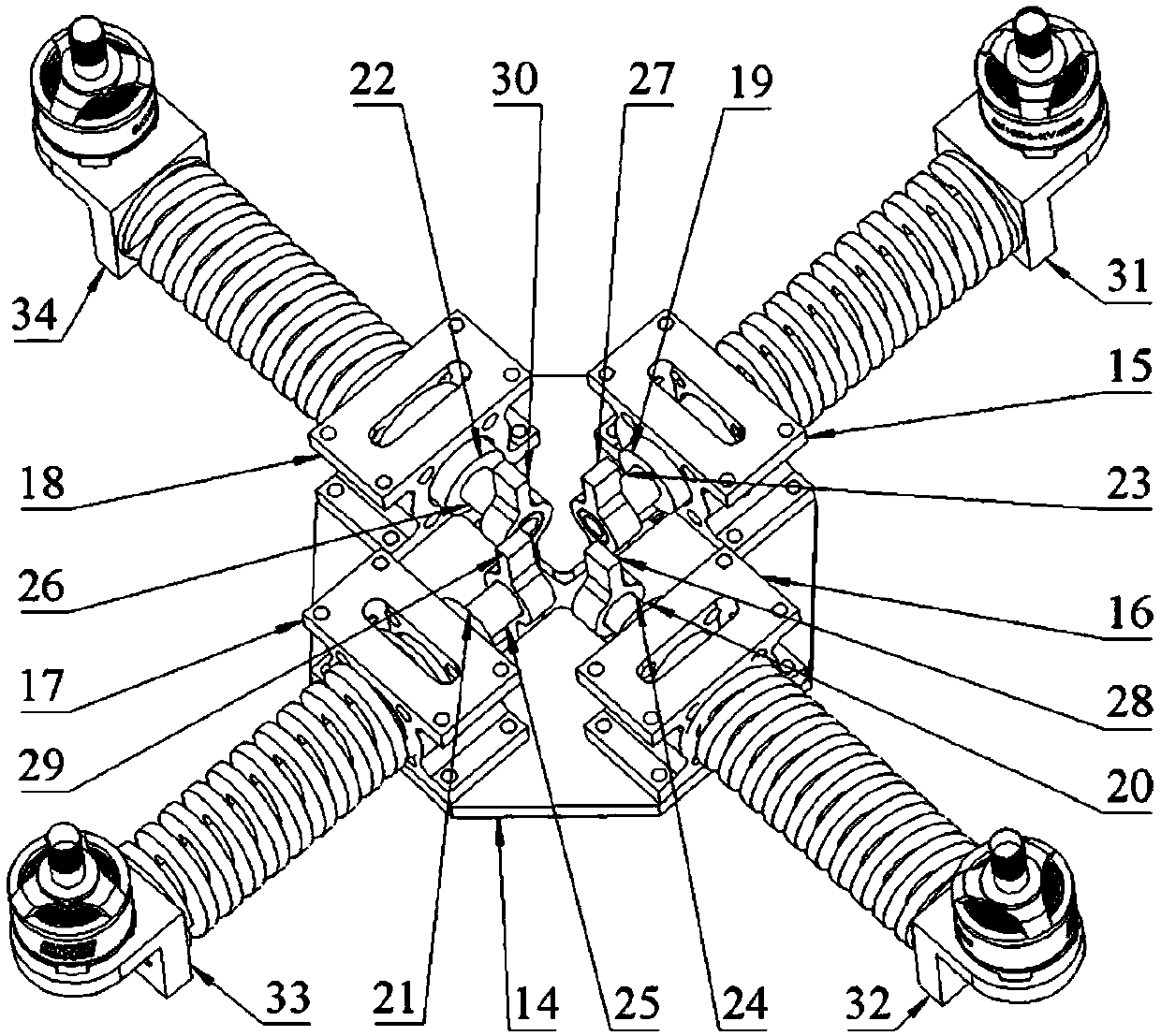
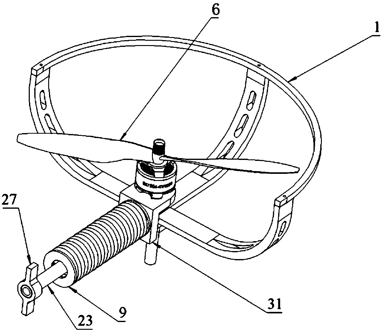
[0055] 1, 2, 3, 4 protective cover; 5, 6, 7, 8 motor; 9, 10, 11, 12 spring; 13 top plate; 14 bottom plate; 15, 16, 17, 18 bearing seat; 19, 20, 21, 22 linear bearing; 23, 24, 25, 26 carbon rod; 27, 28, 29, 30 support seat; 31, 32, 33, 34 motor seat.

[0056] figure 1 , figure 2 Shown, a kind of passive anti-collision shock-absorbing multi-rotor unmanned aerial vehicle, four machine arms of the same structure are evenly arranged along the same circumference on the bottom plate 14, and each machine arm structure is: the bearing seat 15 is fixed on the bottom plate 14 by bolts Above, the linear bearing 19 is installed in the bearing seat 15, the inner end of the carbon rod 23 passes through the linear bearing 19 and is slidably arranged on the linear bearing 19, the outer end of the carbon rod 23 is fixedly connected with a motor seat 31, and the motor 5 is installed on the motor seat 31, the r...


PUM


Abstract

The invention discloses a passive anti-collision damping multi-rotor drone. Multiple engine arms of same structures are evenly arranged on a baseboard in a concyclic mode, according to the structure of each engine arm, a bearing base is fixed to the baseboard through bolts, a linear bearing is installed in the bearing base, an inner end of a carbon rod penetrates through the linear bearing, the carbon rod is arranged on the linear bearing in a sliding mode, a motor base is fixedly connected with an outer end of the carbon rod, a motor is installed on the motor base, a rotor are installed on amotor shaft, the carbon rod is sleeved with a spring, and the spring abuts between the bearing base and the motor base. The passive anti-collision damping multi-rotor drone has the following characters that the structure is simple, and the whole drone is light in weight; collision can be effectively resisted, and a damping effect is good; after being collided, the passive anti-collision damping multi-rotor drone can fast restore an initial state, so that flying of the drone is safer and more reliable.

Description

technical field [0001] The invention relates to a rotor unmanned aerial vehicle, particularly a quadrotor and multi-wing (six-wing, eight-wing, etc.) unmanned aerial vehicle with anti-collision and shock absorption functions. Background technique [0002] Multi-rotor UAV is a new concept weapon equipment in rapid development, which has the advantages of flexible maneuvering, fast response, unmanned flight, and low operation requirements. By carrying multiple types of sensors, drones can realize real-time image transmission and detection of high-risk areas, which is a powerful supplement to satellite remote sensing and traditional aerial remote sensing. At present, the scope of use of drones has been expanded to three major fields: military, scientific research, and civilian use, and it is widely used in fields such as electric power, communication, meteorology, agriculture, ocean, and exploration. [0003] It is precisely because of the diversity of the environment and the ...

Claims


Application Information

Patent Timeline
IPC IPC(8): B64C27/08B64C27/20
CPCB64C27/001B64C27/006B64C27/08B64C27/20B64U10/10
Inventor 李斌斌马磊黄德青黄敏季海梦
Owner SOUTHWEST JIAOTONG UNIV
Why Eureka
Try Eureka