
Dimples lifting pipe for mining deep-sea mineral resources

a technology of deep-sea mineral resources and lifting pipes, which is applied in fluid dynamics, mechanical machines/dredgers, transportation and packaging, etc., can solve the problems of difficult mining using collection devices and lifting pumps, and technical difficulties in the entire lifting system, and achieve the effect of reducing drag

Inactive Publication Date: 2012-09-04
KOREA INST OF GEOSCI & MINERAL RESOURCES
View PDF5 Cites 2 Cited by
  • Summary
  • Abstract
  • Description
  • Claims
  • Application Information

AI Technical Summary

Benefits of technology

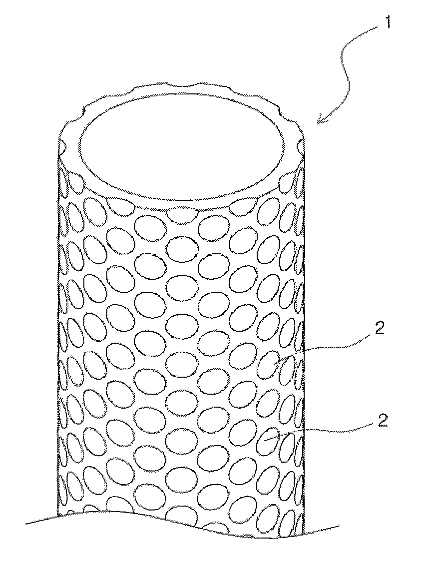
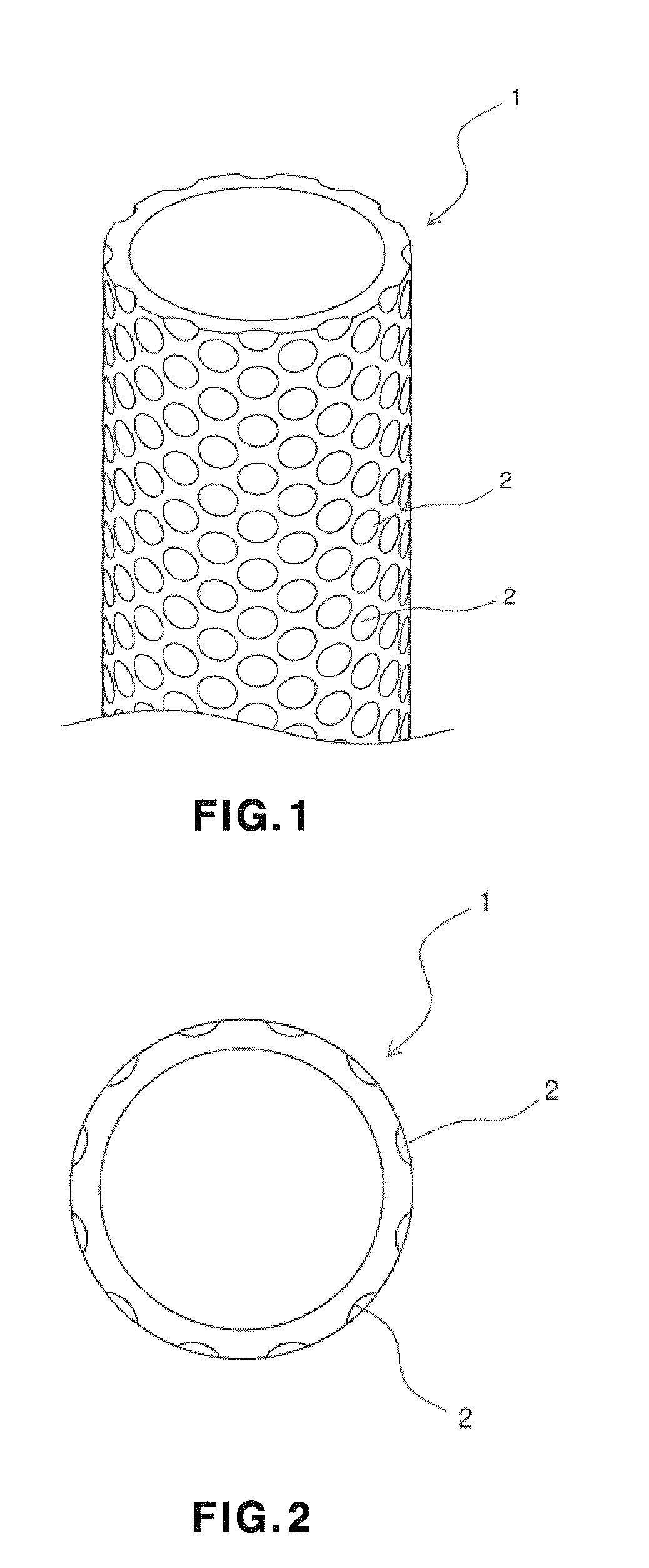
[0009]Accordingly, the present invention has been made keeping in mind the above problems occurring in the prior art, and an object of the present invention is to provide a lifting pipe which is part of a system for mining deep-sea manganese nodules and which has dimples on the outer circumferential surface thereof, so that turbulent flows are generated, thereby reducing drag caused by ocean currents of the deep sea.
[0010]In order to accomplish the above object, the present invention provides a dimpled lifting pipe for mining deep-sea mineral resources, the dimpled lifting pipe being used in a manganese nodule mining system including a collection device for collecting deep-sea manganese nodules and a lifting pump, wherein dimples are formed on the outer circumferential surface of the dimpled lifting pipe, so that turbulent flows are generated, thereby reducing drag caused by ocean currents of the deep sea.

Problems solved by technology

Accordingly, these prior art lifting pipes vibrate due to ocean currents of the deep sea and such vibrations make stable mining using collection devices and lifting pumps difficult due to the vibrations of the lifting pipes and cause technical difficulties to the entire lifting system.

Method used


Image

  • Dimples lifting pipe for mining deep-sea mineral resources
  • Dimples lifting pipe for mining deep-sea mineral resources
  • Dimples lifting pipe for mining deep-sea mineral resources

Examples


embodiment 1

Flow Structure within a Rectangular Duct on One Surface of which Dimples are Formed

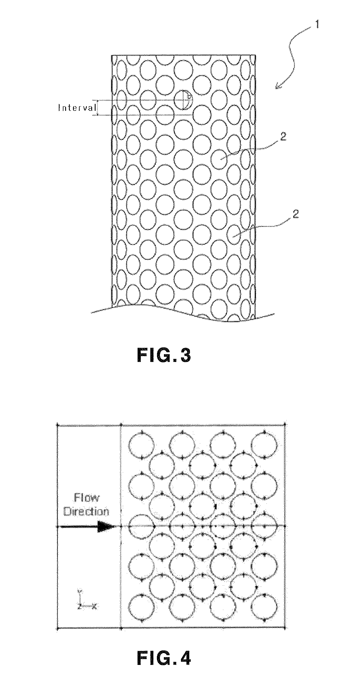
[0048]FIG. 4 is a schematic diagram showing a flow structure within a rectangular duct on one surface of which dimples are formed. On the dimpled surface, dimples are arranged in seven columns in an alternating fashion. The height within the rectangular duct and the print diameter of the dimples are all 0.0508 m, and the depth of the dimples is 0.01524 m. The ratio of the depth of the dimples to the print diameter of the dimples is 0.3, and the hydraulic diameter of the duct is 0.0942 m. A smooth, non-dimpled duct is placed upstream of the dimpled surface duct, and is 1.2 m in length.

[0049]The inlet velocity of air is 4.43 m / s, and the intensity of a turbulent flow is 0.5%. The energy equation was not taken into consideration, and the computational grid of a surface taken in the flow direction is shown in FIG. 5. The computational results were improved by concentrating the grids on the wall surface an...

embodiment 2

Two-Dimensional Flow Around a Circular Cylinder

[0053]FIG. 9 is a schematic diagram of a two-dimensional circular cylinder. The length of the inlet thereof is 40 times the diameter of the cylinder. The cylinder is a circle at the center of this drawing, and a flow field around the cylinder is present within a square domain. The inlet velocity is uniform. For Re=150, a laminar flow was analyzed. Water with a constant viscosity value and a constant density value was selected as a working fluid.

[0054]FIG. 10 shows results of a flow field around the cylinder at time=7670 sec. and Re=150. A fluid flow generated a von Karman vortex street while passing around the cylinder. This vortex street was subjected to the periodic generation, growth and destruction thereof in the wake behind the cylinder.

[0055]The drag coefficient is defined as follows:

[0056]CD=FD12⁢ρ⁢⁢u02⁢A(1)

where ρ is the density of water and u0 is the velocity of the water at the inlet. A is the area of the projected cylinder, a...

embodiment 3

Analysis of a Flow Field of a Two-Dimensional Cylinder

[0057]In this embodiment, two-dimensional circular dimples are formed on the outer surface of a cylinder identical to that used in Embodiment 2. The Reynolds number is 2000, and this range corresponds to a laminar flow region. A total of 12 dimples are formed on the outer wall of the cylinder, and each of the dimples forms an angle of 30 degrees with a neighboring dimple. The ratio of the depth of the dimples to the print diameter of the dimples is in the range of 0.15-0.35.

[0058]FIG. 11 is a schematic diagram of a lifting pipe with dimples. The shape of the dimples is illustrated in this drawing. In this drawing, the print diameter of the dimples is 1 cm, and the depth of the dimples is in the range of 0.15-0.35 cm. A flow flows from the left side of this drawing to the right side thereof. In the foregoing description, the reason why the depth of the dimples is limited within the range of 0.15-0.35 cm on the basis of a print dia...


PUM


Abstract

Disclosed herein is a lifting pipe which is used in a manganese nodule mining system including a collection device for collecting deep-sea manganese nodules and a lifting pump and which has a structure in which dimples are formed on the surface of the lifting pipe so as to reduce drag so that the lifting pipe is less influenced by flows of ocean current. The dimpled lifting pipe includes dimples that are formed on the outer circumferential surface of the dimpled lifting pipe, so that turbulent flows are generated, thereby reducing drag caused by ocean currents of a deep sea.

Description

CROSS-REFERENCE TO RELATED APPLICATION[0001]This application claims the priority of Republic of Korea Application No. 10-2009-0005241, filed Jan. 21, 2009. The disclosure of the prior application is hereby incorporated herein in its entirety by reference.BACKGROUND OF THE INVENTION[0002]1. Field of the Invention[0003]The present invention relates generally to a dimpled lifting pipe for mining deep-sea mineral resources, and, more particularly, to a lifting pipe which is used in a manganese nodule mining system including a collection device for collecting deep-sea manganese nodules and a lifting pump and which has a structure in which dimples are formed on the surface of the lifting pipe so as to reduce drag so that the lifting pipe is less influenced by flows of ocean current.[0004]2. Description of the Related Art[0005]Due to an increase in the global demand for mineral resources, marine mineral resources are attracting attention as new alternatives. Of these marine mineral resourc...

Claims


Application Information

Patent Timeline
Patent Type & Authority Patents(United States)
IPC IPC(8): E02F3/92
CPCF16L1/15F16L9/006E21C50/00E02F7/10
Inventor YOON, CHI-HOPARK, JONG-MYUNGPARK, YONG-CHAN
Owner KOREA INST OF GEOSCI & MINERAL RESOURCES
Learn More