Processing liquid applying apparatus and image-forming apparatus

a technology of processing liquid and applying apparatus, which is applied in the direction of electrographic process apparatus, coatings, instruments, etc., can solve the problems of blurred images and/or color development, inability to maintain constant spacing distance between the abutting member and the applying roller, and inability to appropriately change spacing distance, etc., to achieve the effect of soaking the processing liquid transferred

Active Publication Date: 2012-08-28
BROTHER KOGYO KK
View PDF17 Cites 1 Cited by
  • Summary
  • Abstract
  • Description
  • Claims
  • Application Information

AI Technical Summary

Benefits of technology

[0009]The present invention has been made in order to solve the problem as described above, an object of which is to provide a processing liquid applying apparatus and an image-forming apparatus provided with the processing liquid applying apparatus which make it possible to preferably adjust the applying amount of a processing liquid with respect to a processing liquid transfer roller in the “transfer mode” and the “cleaning mode” respectively.
[0011]In this arrangement, the distance between the downstream wall and the processing liquid transfer roller, which is provided when the downstream wall is positioned at the downstream wall second position, is greater than that provided when the downstream wall is positioned at the downstream wall first position. Therefore, the applying amount of the processing liquid to be applied to the surface of the processing liquid transfer roller is increased when the downstream wall is positioned at the downstream wall second position as compared with when the downstream wall is positioned at the downstream wall first position.
[0012]The present teaching is constructed as explained above. The applying amount of the processing liquid, with which the processing liquid transfer roller is applied, can be preferably adjusted in each of the “transfer mode” and the “cleaning mode”. In other words, in the “transfer mode” in which the processing liquid is transferred to the transfer medium, the applying amount of the processing liquid with respect to the processing liquid transfer roller can be adjusted to be “relatively small”, for example, in order to quicken the drying of the processing liquid transferred to the transfer medium. On the other hand, in the “cleaning mode” in which the surface of the processing liquid transfer roller is washed, the applying amount of the processing liquid with respect to the processing liquid transfer roller can be adjusted to be “relatively large” in order to wash out the foreign matter (for example, paper dust or paper powder) adhered to the processing liquid transfer roller.

Problems solved by technology

In this situation, the inks are not preferably deposited onto the printing paper depending on the type of the inks or the printing paper, and the image is blurred and / or the color development is deteriorated in some cases.
Therefore, the spacing distance between the abutting member and the applying roller cannot be maintained to be constant and / or the spacing distance cannot be appropriately changed.
For example, when the applying amount of the processing liquid is excessively increased in the “transfer mode” in which the processing liquid is transferred from the applying roller to the sheet member, it is feared that a long period of time may be required to dry the processing liquid transferred to the sheet member and / or the processing liquid, which remains on the surface of the applying roller, may inhibit the next transfer process.
Therefore, a tendency arises such that the applying amount of the processing liquid is not only stabilized, but the applying amount is also increased undesirably.
In the case of the conventional technique described above, it is impossible to appropriately change the spacing distance between the abutting member and the applying roller.
Therefore, it is impossible to intentionally increase the applying amount of the processing liquid in the “cleaning mode”, and it is impossible to obtain any sufficient cleaning effect.

Method used


Image

  • Processing liquid applying apparatus and image-forming apparatus
  • Processing liquid applying apparatus and image-forming apparatus
  • Processing liquid applying apparatus and image-forming apparatus

Examples


first embodiment

Overall Arrangement of Image-Forming Apparatus

[0023]An image-forming apparatus 10 includes a casing 14, a paper feed cassette 16, a liquid discharge apparatus 18, a transport apparatus 20, a processing liquid applying apparatus 22, a detecting unit 24, and a control unit 26, and a processing liquid R (FIG. 4) is applied to the printing paper 12 as the “transfer medium” or the medium subjected to the transfer, and then the inks as the “liquids” are discharged to the surface of the printing paper 12 to form an image.

[0024]The casing 14 is a box-shaped member which accommodates the constitutive parts as described above. An opening 14a through which the paper feed cassette 16 is taken in and out and a printing paper discharge port 14b through which the printing paper 12 is discharged are formed on the side surface of the casing 14. A paper discharge tray 28, which receives the printing paper 12 discharged from the printing paper discharge port 14b, is attached under or below the printin...

second embodiment

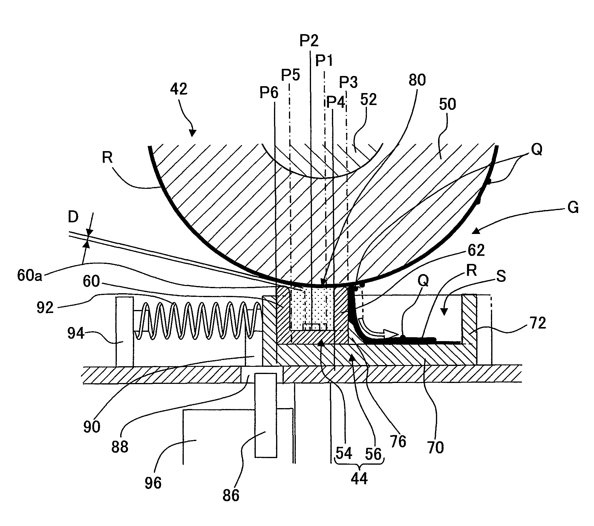
[0059]In a processing liquid applying apparatus 108 according to a second embodiment, as shown in FIG. 8, rotary shafts 110 of a applying member 44 are formed at both end portions in the printing paper widthwise direction Y of the applying member 44, and a motor (not shown) is connected to the rotary shaft 110. The angle of rotation of the motor is controlled by the control unit 26, and thus the “transfer mode (solid lines shown in FIG. 8)” and the “cleaning mode (two-dot chain lines shown in FIG. 8)” are switched. In other words, the distance D between the downstream wall 60 and the processing liquid transfer roller 42 in the “cleaning mode” is greater than the distance D in the “transfer mode”. Further, the contact pressure of the upstream wall 62 with respect to the processing liquid transfer roller 42 in the “cleaning mode” is smaller than the contact pressure in the “transfer mode”. In this way, in the second embodiment, it is possible to more finely adjust the “distance” D bet...

third embodiment

[0060]In a processing liquid applying apparatus 112 according to a third embodiment, as shown in FIG. 9, a pressing member 114, which includes, for example, an electromagnetic solenoid or an air cylinder and which presses the applying member 44 toward the side of the processing liquid transfer roller 42, is arranged under or below the applying member 44. In the “waiting state” in which the drying and the increase in viscosity of the processing liquid R accommodated in the processing liquid accommodating cap 54 is avoided to preferably maintain the viscosity of the processing liquid R when the printing operation of the image-forming apparatus 10 is not performed, the applying member 44 is pressed by the pressing member 114. Accordingly, the forward ends of the respective walls 60, 62, 64 of the applying member 44 are allowed to abut against the surface of the processing liquid transfer roller 42 in a capping state in a liquid-tight manner. Therefore, in the “waiting state”, it is pos...


PUM


Abstract

A processing liquid applying apparatus includes a processing liquid transfer roller which transfers a processing liquid to a transfer medium while rotating in a predetermined direction; a processing liquid applying section which applies the processing liquid to a surface of the processing liquid transfer roller; a downstream wall which is positioned on a downstream side in a rotating direction of the processing liquid transfer roller with respect to the processing liquid applying section; and a downstream wall moving mechanism which moves the downstream wall between a downstream wall first position at which the downstream wall is positioned when the processing liquid is transferred to the transfer medium and a downstream wall second position at which the downstream wall is positioned when the surface of the processing liquid transfer roller is washed with the processing liquid.

Description

CROSS REFERENCE TO RELATED APPLICATION[0001]The present application claims priority from Japanese Patent Application No. 2009-045832, filed on Feb. 27, 2009, the disclosure of which is incorporated herein by reference in its entirety.BACKGROUND OF THE INVENTION[0002]1. Field of the Invention[0003]The present invention relates to a processing liquid applying apparatus which applies a processing liquid to a surface of a processing liquid transfer roller and transfers the processing liquid to a transfer medium (for example, printing paper and recording sheet), and an image-forming apparatus provided with the processing liquid applying apparatus.[0004]2. Description of the Related Art[0005]For example, in an image-forming apparatus (for example, printer and facsimile) based on the “ink-jet system”, the inks, which are discharged from the nozzles, are adhered or deposited onto the surface of the printing paper. In this situation, the inks are not preferably deposited onto the printing pa...

Claims


Application Information

Patent Timeline
Patent Type & Authority Patents(United States)
IPC IPC(8): B41J2/175
CPCB41J2/2114B41J11/0015
Inventor SHIMIZU, YOICHIRONISHIZAKI, MASAHIROMORITA, YOSHITSUGUKUBO, TOMOYUKI
Owner BROTHER KOGYO KK
Why Eureka
Try Eureka