
Device and method for analyzing a sample

a sample surface and device technology, applied in the direction of isotope separation, particle separator tubes, electric discharge tubes, etc., can solve the problems of ions to be produced with very high energy and liable to fragment, and achieve the effect of optimizing the signal strength produced

Active Publication Date: 2012-07-31
WATERS TECH CORP
View PDF24 Cites 1 Cited by
  • Summary
  • Abstract
  • Description
  • Claims
  • Application Information

AI Technical Summary

Benefits of technology

[0019]Preferably, the outlet is movable, enabling optimization of signal strength produced by the detector.

Problems solved by technology

These methods, however, often caused ions to be produced with very high energy, which left them liable to fragment.
The analysis of solid samples and surfaces with on analysis devices has always provided particular challenges, as traditional soft ionization techniques are appropriate only to the analysis of liquid samples or samples held in solution.

Method used


Image

  • Device and method for analyzing a sample
  • Device and method for analyzing a sample
  • Device and method for analyzing a sample

Examples


example 1

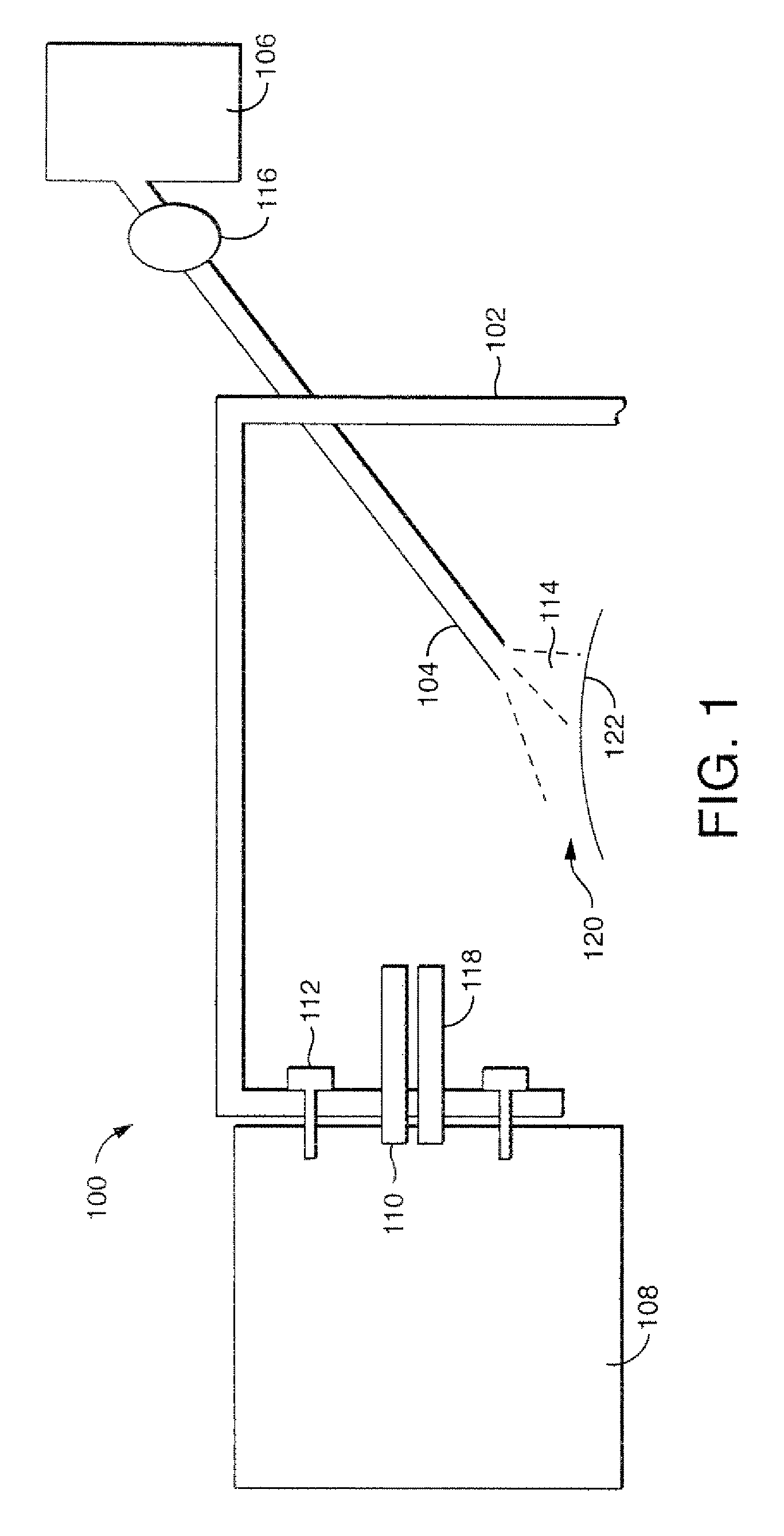
[0097]An analysis of a tablet of Benadryl, a commercial antihistamine was performed using a device substantially as shown in FIG. 1. The active chemical ingredient in Benadryl is diphenhydramine. A heated inlet tube was attached to a standard Z-Spray interface to an orthogonal TOF mass spectrometer (Waters, Mass.). The inlet was heated to 90° C. and raised to a potential of 65V. A stainless steel capillary tube was used as an outlet. A Benadryl tablet was placed in the sampling region and exposed to a jet of Joule-Thomson cooling CO2. The arrival time spectrum shown in FIG. 6 shows the signal corresponding to diphenhydramine obtained at m / z 256.17, together with the adjacent C13 isotope peak.

example 2

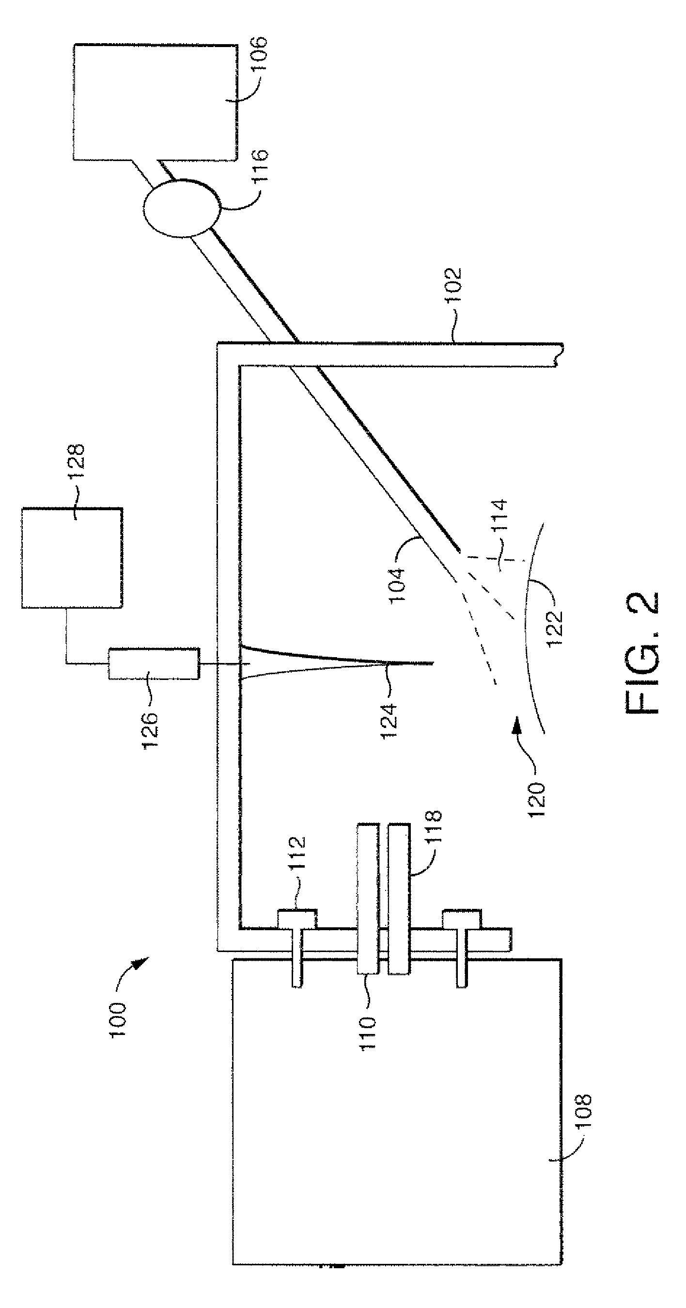
[0098]An analysis of a tablet of Benadryl was performed using a device substantially as shown in FIG. 2. A heated inlet tube was attached to a standard Z-Spray interface to an orthogonal TOF mass spectrometer (Waters, Mass.). The inlet was heated to 90° C. and raised to a potential of 65V. A stainless steel capillary tube was used as an outlet. The discharge member was raised to a potential of 4000V. A Benadryl tablet was placed in the sampling region and exposed to a jet of Joule-Thomson cooling CO2. The arrival time spectrum shown in FIG. 7 shows the signal corresponding to diphenhydramine obtained at m / z 256.17, together with the adjacent C13 isotope peak. Signal strength was found to be 30-50 times greater than when using the device described in Example 1.

example 3

[0099]An analysis of a tablet of Benadryl was performed using a device substantially as shown in FIG. 2. A heated inlet tube was attached to a standard Z-Spray interface to an orthogonal TOF mass spectrometer (Waters, Mass.). The inlet was heated to 90° C. and raised to a potential of 65V. A stainless steel capillary tube was used as an outlet. The area impacted by the CO2 jet was blanketed with an aerosol formed from an eluent comprising methanol with 0.1% acetic acid. The eluent flowed into the aerosol source at 6 μL / min and was nebulized with nitrogen gas. A Benadryl tablet was placed in the sampling region and exposed to a jet of Joule-Thomson cooling CO2.


PUM


Abstract

Embodiments of the invention relate to a device for analyzing a sample surface Comprising an outlet and a frame. The outlet is for forming a jet of gas, the jet forming a sampling region for receiving one or more sample surfaces, and the frame holding the outlet and being adapted to receive a detector means. The detector means has an inlet. In use, the jet produces desorbed sample from sample surfaces received in the sample area. At least a portion of the desorbed sample is ionized to produce one or more sample ions. The frame holds the outlet with respect to the sample ions and produce a signal indicative of the composition of the sample ions.

Description

CROSS REFERENCE TO RELATED APPLICATIONS[0001]This application is the National Stage of International Application No. PCT / US2008 / 052768, filed Feb. 1, 2008, which claims priority to and benefit of U.S. Provisional Patent Application Ser. No. 60 / 887,897, filed Feb. 2, 2007, U.S. Provisional Patent Application Ser. No. 60 / 911,566, filed Apr. 13, 2007 and U.S. Provisional Patent Application Ser. No. 60 / 941,004, filed May 31, 2007. The entire contents of these applications are incorporated herein by reference.STATEMENT WITH RESPECT TO FEDERAL SPONSORSHIP[0002]The present invention was made without Federal sponsorship or funds.FIELD OF THE INVENTION[0003]The present invention relates to a device and method for analyzing the surface of a sample.BACKGROUND OF THE INVENTION[0004]Ion analysis devices such as mass spectrometers have been used to great effect to analyze and characterize samples both simple and complex. Such devices require samples to be ionized so that mass to charge ratio (m / z...

Claims


Application Information

Patent Timeline
Patent Type & Authority Patents(United States)
IPC IPC(8): H01J49/00
CPCH01J49/0463
Inventor JARRELL, JOSEPH A.TOMANY, MICHAEL J.
Owner WATERS TECH CORP
Learn More