Discharge element with discharge-control electrode and the control circuit thereof

a technology of discharge control electrode and control circuit, which is applied in the direction of electrostatic control tubes, process and machine control, instruments, etc., can solve the problems of lightning damage cannot be prevented, inadequate discharge performance, etc., and achieve the effect of low residual voltage characteristic and excellent discharge performan

Active Publication Date: 2012-07-24
SURGELAB KOREA
View PDF7 Cites 5 Cited by
  • Summary
  • Abstract
  • Description
  • Claims
  • Application Information

AI Technical Summary

Benefits of technology

[0025]A discharge element having a discharge-control electrode and a control circuit of the discharge element according to the present invention is a new discharge element and a control circuit totally different from the prior art, which has an excellent discharge performance even at a low voltage applied at high speed, and has a low residual voltage characteristic.
[0026]Furthermore, a lightning / surge protector having a discharge element having a discharge-control electrode and a discharge-control element according to the present invention may provide a low residual voltage characteristic that the equipment can sufficiently survive even at an induced surge, thereby perfectly protecting the equipment from lightning, as well as provide an opportunity for preparing for a ground of enabling the unification of various international regulations through providing a discharge element discharged at low voltage.

Problems solved by technology

Accordingly, for a testing according to international regulations that protection elements based on PSTN should be discharged within 600 V in the ITU-T, discharge elements typically used against a characteristic of transient voltage which is quickly applied, such as an induced surge, are all inadequate, and it is reality that lightning damage cannot be prevented even when a terminal box or MDF protection plug is actually installed in a building.

Method used


Image

  • Discharge element with discharge-control electrode and the control circuit thereof
  • Discharge element with discharge-control electrode and the control circuit thereof
  • Discharge element with discharge-control electrode and the control circuit thereof

Examples


Embodiment Construction

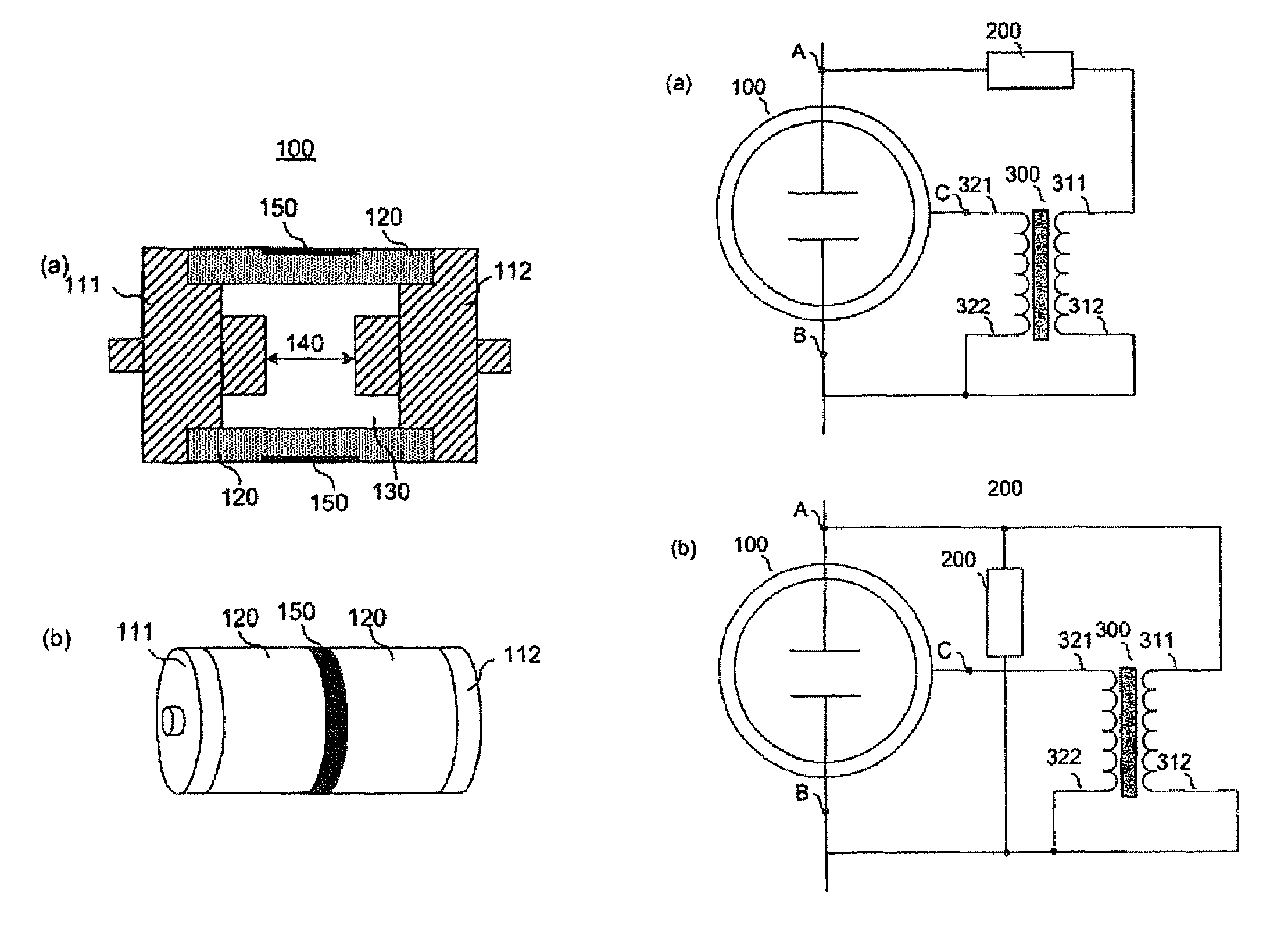
of Main Elements]100: discharge element having discharge-control electrode111, 112: discharge-control electrode120: ceramic insulator130: discharge-assisting material (gas)140: discharge gap150, 151, 152: discharge-control electrode113: earth electrode200: limiting element300: high voltage transformer

BEST MODE

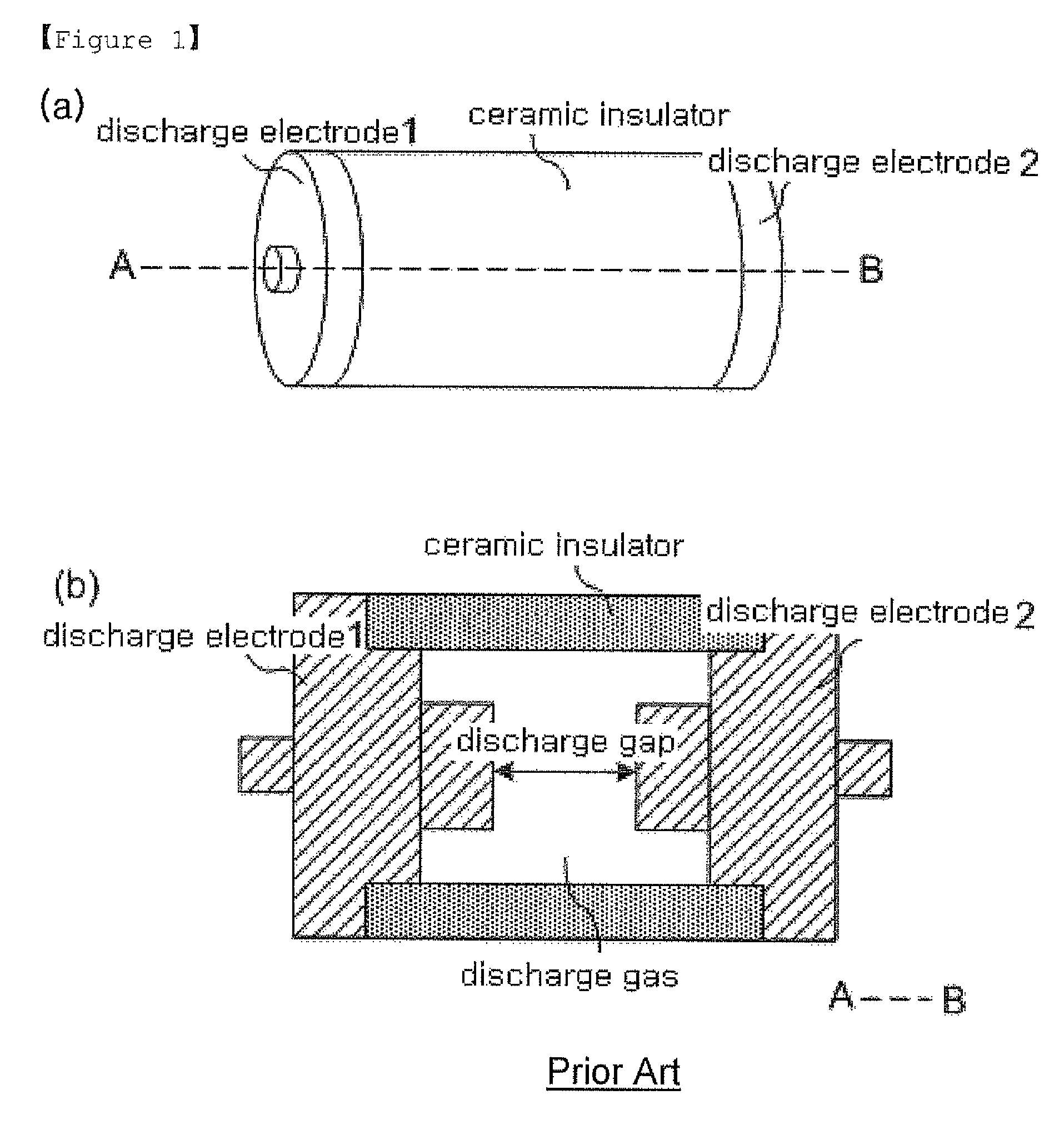
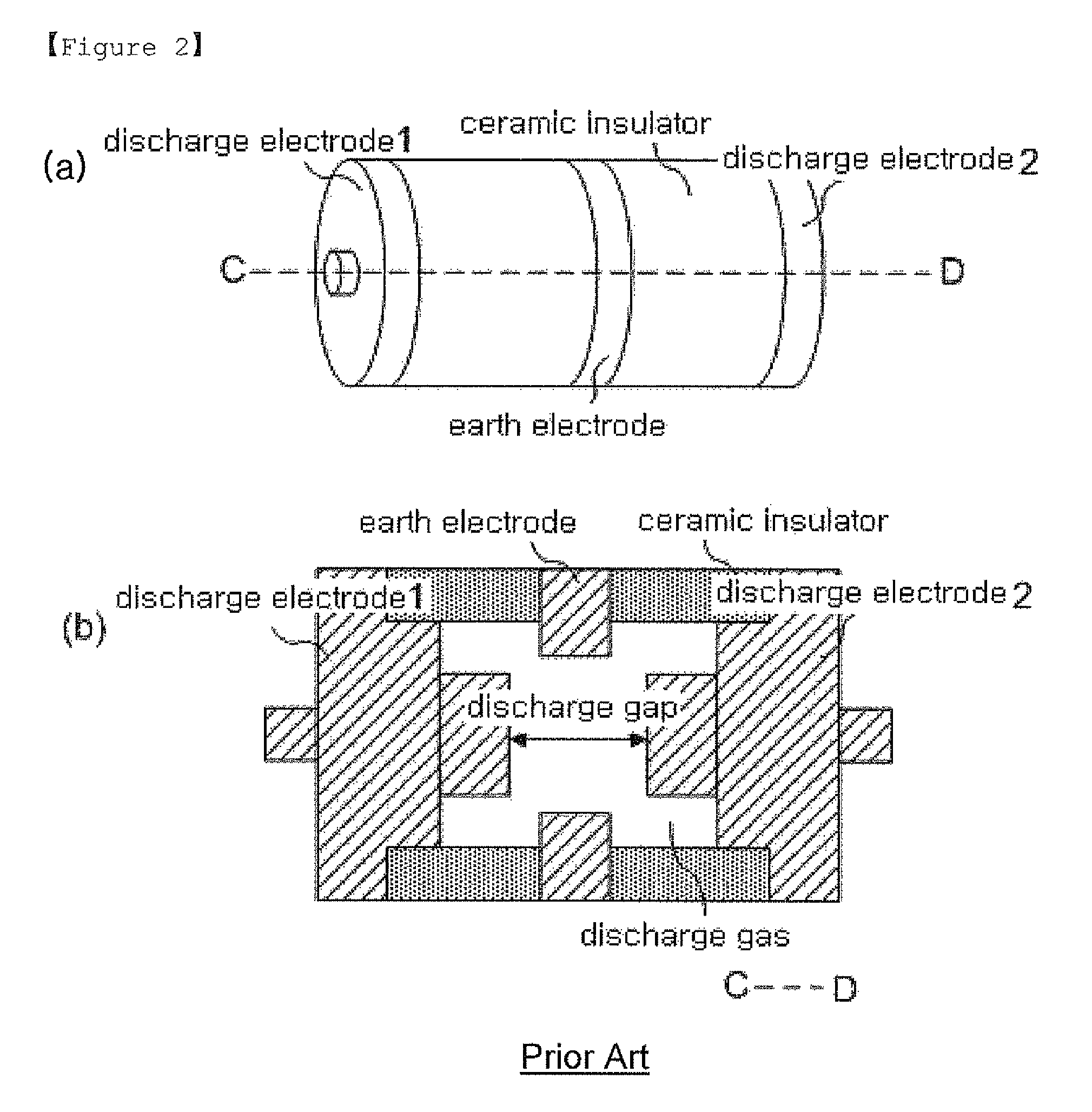
[0040]Hereinafter, a discharge element having a discharge-control electrode and a driving circuit for driving the discharge element according to the present invention will be described in detail with reference to accompanying drawings. The drawings illustrated below are provided as an example to fully convey the thought of the invention to those skilled in the art. Accordingly, the present invention is not limited to the drawings illustrated below, and may be realized by other alternative arrangements. Furthermore, the same reference numerals represent the same structural elements throughout the specification.

[0041]Here, unless specifically defined otherwise, all technical or s...


PUM


Abstract

The present invention relates to a new discharge element having a discharge-control electrode for inducing a discharge even at low voltage by improving a characteristic in which a discharge element may not be discharged against a fast transient voltage when it is at low voltage, and more specifically, the discharge element having a discharge-control electrode according to the present invention comprises an airtight cylinder formed with a ceramic insulation material, a pair of discharge electrodes arranged for facing an end opening of the airtight cylinder, a discharge gap formed between the pair of discharge electrodes, a discharge-assisting material filled inside the airtight cylinder, and a discharge-control electrode in contact with the airtight cylinder and physically separated from the discharge-assisting material, wherein a discharge between the pair of discharge electrodes is induced by a control voltage applied through the discharge-control electrode.

Description

TECHNICAL FIELD[0001]The present invention relates to a new discharge element having a discharge-control electrode for inducing a discharge even at low voltage by improving a characteristic in which a discharge element may not be discharged against a fast transient voltage when it is at low voltage, and a driving circuit for driving a discharge element according to the present invention.BACKGROUND ART[0002]FIG. 1 illustrates a 2-pole discharge element in the prior art, and the element includes discharge electrode 1 and discharge electrode 2 at both ends of a cylindrical tube made of a ceramic insulator, and a discharge gap is formed inside the tube, and it has a structure filled with a discharge-assisting material (gas) inside the discharge gap.[0003]In a discharge element as described above, when high voltage is applied between discharge electrode 1 and discharge electrode 2, a discharge-assisting material filled in the discharge gap starts a glow discharge while being ionized, and...

Claims


Application Information

Patent Timeline
Patent Type & Authority Patents(United States)
IPC IPC(8): H01J61/54
CPCH01J61/54H01T2/02H01J61/56H05B41/02
Inventor KIM, SEONHO
Owner SURGELAB KOREA
Why Eureka
Try Eureka