
Golf ball

a technology of golf ball and ball body, which is applied in the field of golf balls, can solve the problems of not having sufficient good ball properties such as durability to cracking and scuffing, and achieve the effects of excellent flight performance, excellent durability to cracking, and low spin ra

Active Publication Date: 2012-07-10
BRIDGESTONE SPORTS
View PDF18 Cites 11 Cited by
  • Summary
  • Abstract
  • Description
  • Claims
  • Application Information

AI Technical Summary

Benefits of technology

[0005]It is therefore an object of the present invention to provide a golf ball which is composed of a solid core, an intermediate layer and a cover, which achieves a low spin rate and has an excellent flight performance, and which also is endowed with an excellent durability to cracking on repeated impact and an excellent scuff resistance.
[0006]The inventors have conducted extensive investigations in order to achieve the above object. As a result, they have discovered that, with regard to the hardness profile of the core in a golf ball having a core, an intermediate layer and a cover, by focusing both on the hardness difference between the surface and center of the core and on the hardness gradient in the core and working to optimize these, and by also optimizing the hardness relationship between the intermediate layer and the cover which encase the core, surprisingly, a lower ball spin rate is achieved on full shots with a driver (W#1) by players such as amateur golfers who do not have a high head speed, thus improving the distance traveled by the ball, in addition to which the ball is also endowed with an excellent durability to cracking on repeated impact and an excellent scuff resistance.

Problems solved by technology

Designing the thickness, hardness and other properties of the respective ball layers in such a way as to maximize these desirable effects is another major challenge.
However, these three-piece solid golf balls leave something to be desired in achieving a low spin rate on shots with a driver, and moreover do not always have sufficiently good ball properties such as durability to cracking and scuff resistance.

Method used


Image

  • Golf ball
  • Golf ball
  • Golf ball

Examples


examples

[0119]Examples of the invention and Comparative Examples are given below by way of illustration, and not by way of limitation.

examples 1 to 3

, Comparative Examples 1 to 4

Formation of Core

[0120]Rubber compositions were formulated as shown in Table 1, then molded and vulcanized under the conditions shown in Table 1 to form cores.

[0121]

TABLE 1ExampleComparative Example1231234CorePolybutadiene A00090000formulationPolybutadiene B7070700707070(pbw)Polybutadiene C2020200202020Polyisoprene rubber10101010101010Zinc acrylate24.223.222.12529.324.224.2Peroxide (1)0000.6000Peroxide (2)1.21.21.20.631.21.2Antioxidant (1)0.10.10.10.100.10.1Antioxidant (2)00000.100Zinc oxide37.437.838.237.536.737.420.5Sulfur00000.100Zinc stearate0000500VulcanizationTemperature (° C.)156156156155156156156Time (minutes)15151515151515Trade names for the chief materials appearing in the table are given below.Polybutadiene A: Available from JSR Corporation under the trade name “BR 01”Polybutadiene B: Available from JSR Corporation under the trade name “BR 730”Polybutadiene C: Available from JSR Corporation under the trade name “BR 51”Polyisoprene rubber: Avai...


PUM


Abstract

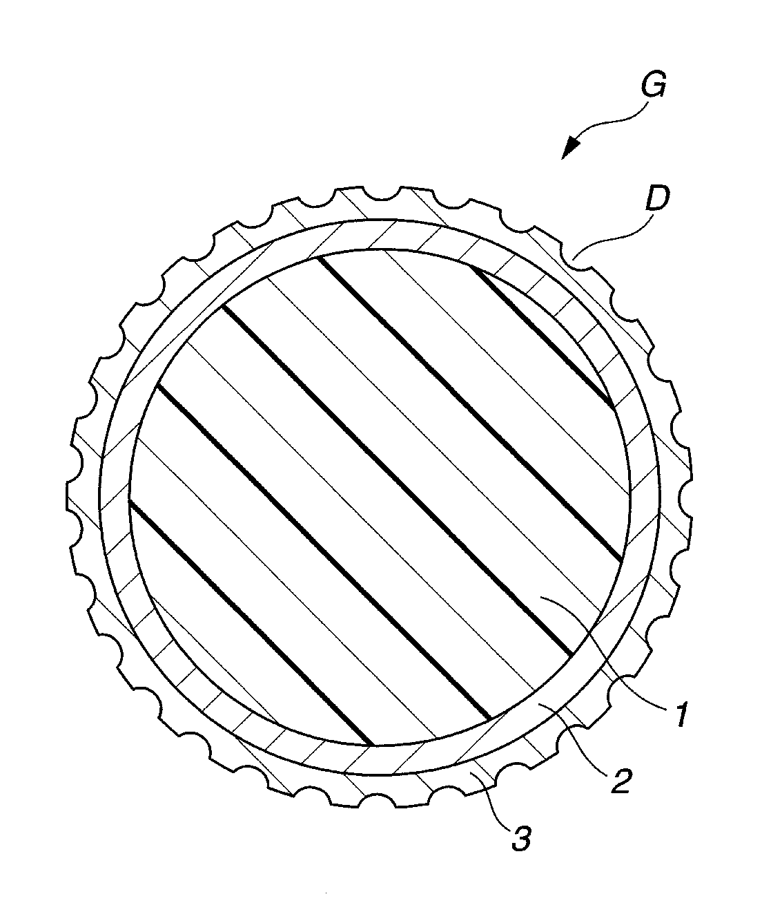
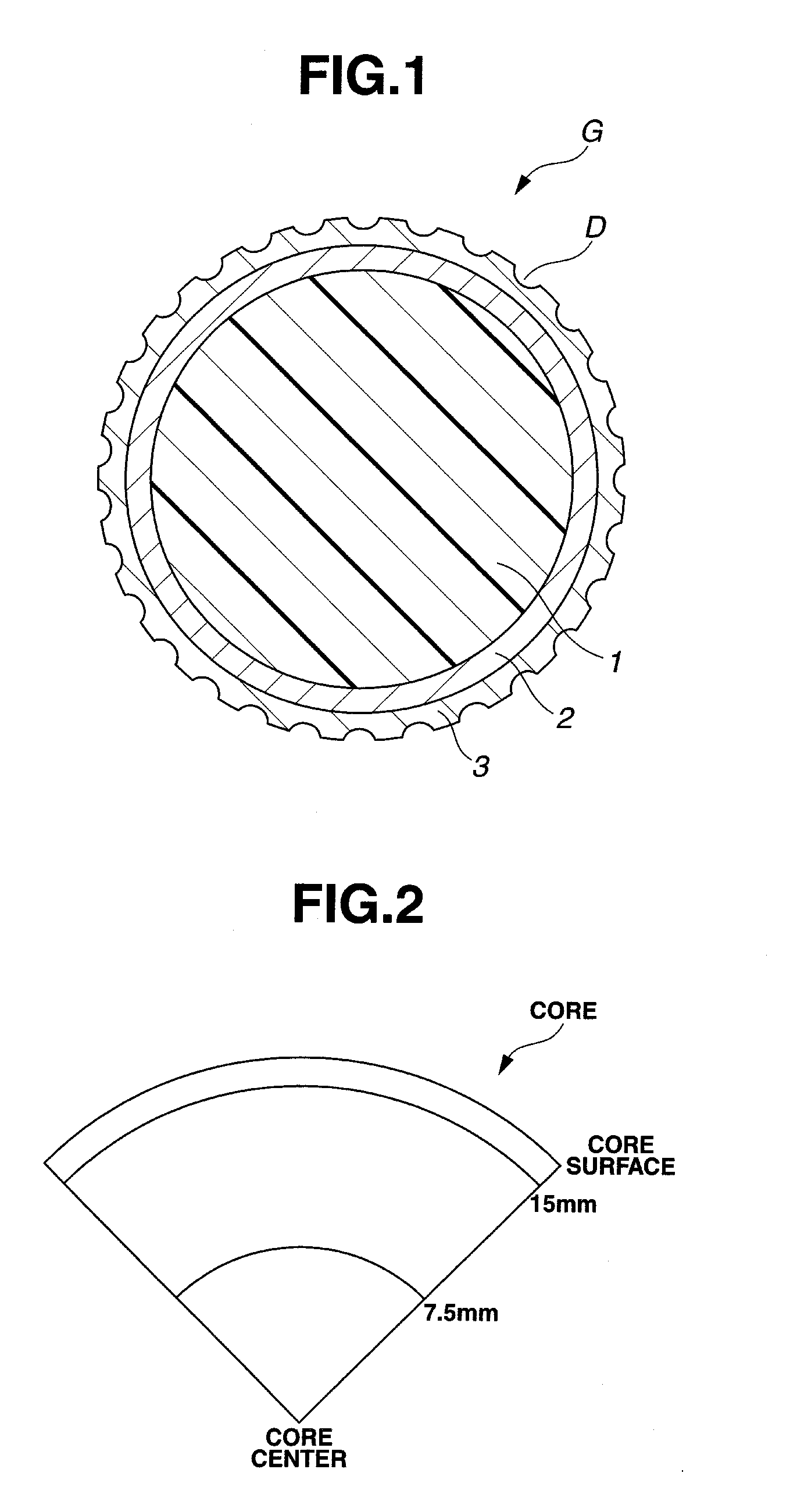
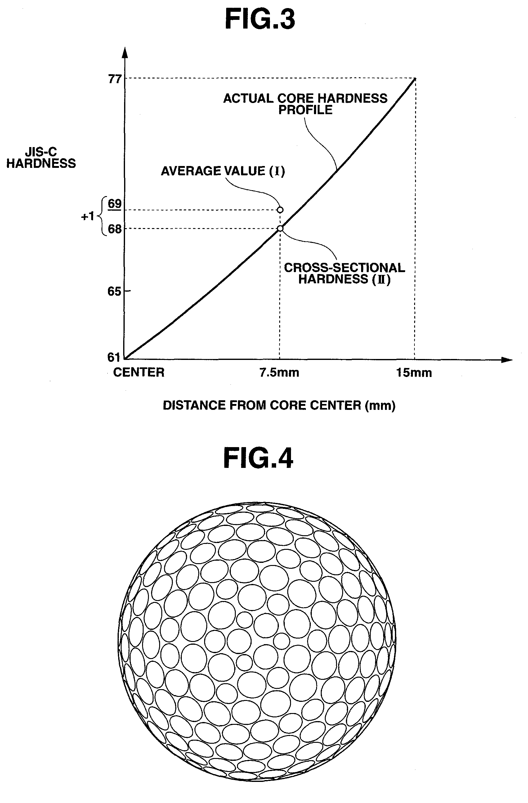
The present invention provides a multi-piece solid golf ball having a core, an envelope layer, an intermediate layer, and a cover, in this order, and has formed on a surface thereof a plurality of dimples. The core has a hardness which gradually increases from a center to a surface thereof, the hardness difference in JIS-C hardness units between the core center and the core surface being at least 15 and, letting (I) be the average value for cross-sectional hardnesses at a position about 15 mm from the core center and at the core center and letting (II) be the cross-sectional hardness at a position about 7.5 mm from the core center, the hardness difference (I)-(II) in JIS-C units being not more than ±2. The envelope layer, intermediate layer and cover have hardnesses which satisfy the condition: cover hardness>intermediate layer hardness>envelope layer hardness.

Description

BACKGROUND OF THE INVENTION[0001]The present invention relates to a golf ball composed of a core, an intermediate layer and a cover that have been formed as successive layers. More specifically, the invention relates to a golf ball which has a good flight performance, a good durability to cracking and a good scuff resistance.[0002]A variety of golf balls have hitherto been developed. Of these, three-piece solid golf balls having an optimized hardness relationship between an intermediate layer and a cover layer which encase the core are in wide use. In recent years, important elements in assessing ball performance include not only the flight performance, but also the durability of the ball to cracking and the scuff resistance—which is the ability to suppress burr formation on the ball surface. Designing the thickness, hardness and other properties of the respective ball layers in such a way as to maximize these desirable effects is another major challenge. Also, with regard to the us...

Claims


Application Information

Patent Timeline
Patent Type & Authority Patents(United States)
IPC IPC(8): A63B37/06
CPCA63B37/0063A63B37/0092A63B37/0075
Inventor WATANABE, HIDEO
Owner BRIDGESTONE SPORTS
Learn More