
Diagnostic apparatus for vehicle cooling system

a technology for diagnosing apparatus and vehicle cooling, which is applied in the direction of instruments, heat measurement, machines/engines, etc., can solve the problem of difficulty in maintaining the proper relationship between the detection value of the front temperature sensor and the detection value of the rear temperature sensor

Inactive Publication Date: 2012-07-10
DENSO CORP
View PDF3 Cites 16 Cited by
  • Summary
  • Abstract
  • Description
  • Claims
  • Application Information

AI Technical Summary

Benefits of technology

The present invention provides a diagnostic apparatus for a vehicle cooling system that can detect unauthorized alterations of a radiator and does not limit the fixing position of temperature sensors to a narrow area. The apparatus includes a front temperature sensor fixed on the front surface of the radiator to detect temperature on the front surface, and a rear temperature sensor fixed on the rear surface of the radiator to detect temperature on the rear surface. The apparatus uses an abnormal diagnosis method to determine if there is an abnormality in the radiator based on the difference between the detection value of the front temperature sensor and the detection value of the rear temperature sensor. The apparatus can easily mount on the vehicle and is effective in detecting abnormalities in the radiator.

Problems solved by technology

If the front temperature sensor and the rear temperature sensor, which are fixed on the authorized radiator, are cut away with the sensor fixing portion and are fixed on the other portion, it is very difficult to maintain the proper relationship between the detection value of the front temperature sensor and the detection value of the rear temperature sensor.

Method used


Image

  • Diagnostic apparatus for vehicle cooling system
  • Diagnostic apparatus for vehicle cooling system
  • Diagnostic apparatus for vehicle cooling system

Examples


Embodiment Construction

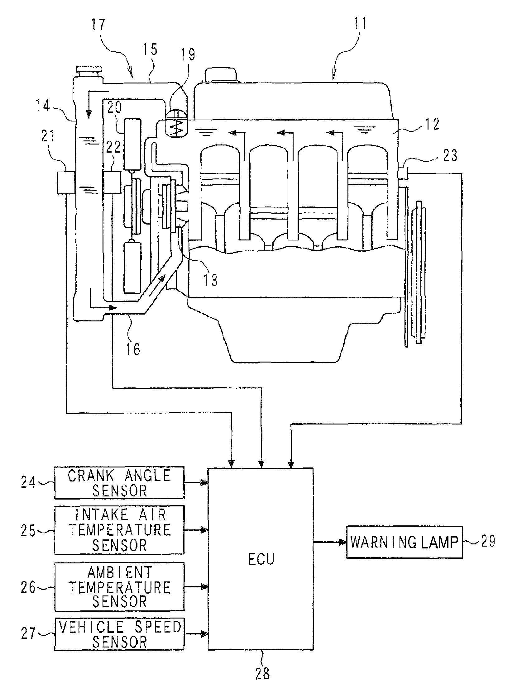
[0023]An embodiment of the present invention will be described hereinafter. Referring to FIGS. 1 to 3, an engine cooling system is explained. As shown in FIGS. 1 and 3, a water pump 13 is provided at an inlet of a coolant passage 12 (water jacket) of an internal combustion engine 11. This water pump 13 is a mechanical pump driven by the engine 11 or an electric pump driven by a motor.

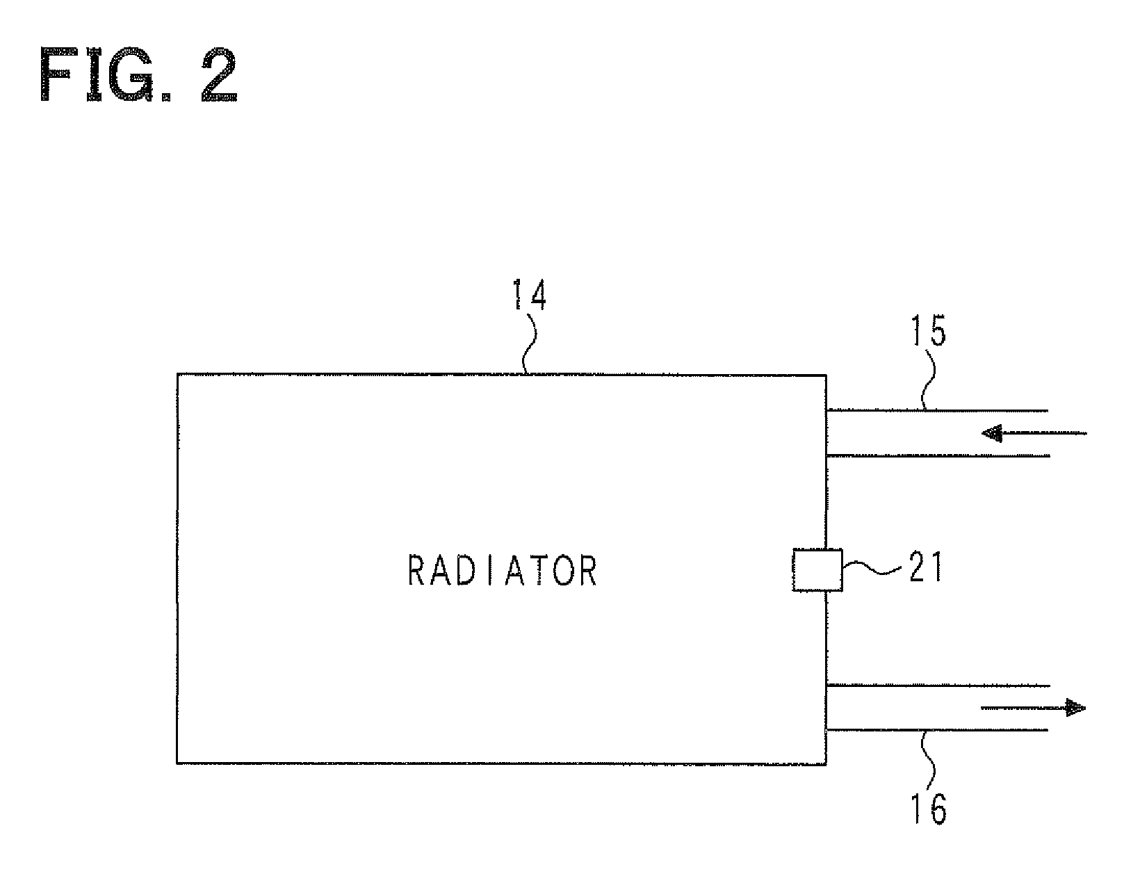
[0024]An outlet of the coolant passage 12 is connected to an inlet of a radiator 14 through a first coolant circulation pipe 15. An outlet of the radiator 14 is connected to an inlet of the water pump 13 through a second coolant circulation pipe 16. Thereby, a coolant circulation circuit 17 is configured, in which the coolant flows through the coolant passage 12, the first coolant circulation pipe 15, the radiator 14, the second coolant circulation pipe 16, the water pump 13, and the coolant passage 12 in this series.

[0025]As shown in FIG. 3, the coolant circulation circuit 17 is provided with a bypass ...


PUM

PropertyMeasurementUnit
temperatureaaaaaaaaaa
areaaaaaaaaaaa
front temperatureaaaaaaaaaa

Abstract

When the driving wind and the cooling wind are generated, based on the phenomenon in which the temperature difference is generated between the front surface and the rear surface of the radiator (14), the temperature difference between the detection value of the rear temperature sensor (22) and the detection value of the front temperature sensor (21) is compared with the abnormality determination value so that it is determined whether the front temperature sensor (21) and the rear temperature sensor (22) are properly fixed on the radiator (14), whereby it is determined whether the abnormality (unauthorized alteration) exists. By setting the abnormality determination value according to the ambient temperature and the vehicle speed, corresponding to a variation in temperature difference between the front surface and the rear surface of the radiator (14), the abnormality determination value is varied to be set at a proper value.

Description

CROSS-REFERENCE TO RELATED APPLICATION[0001]This application is based on Japanese Patent Application No. 2008-235894 filed on Sep. 16, 2008, the disclosure of which is incorporated herein by reference.FIELD OF THE INVENTION[0002]The present invention relates to a diagnostic apparatus for a vehicle cooling system which mounts a radiator provided with a function of purifying ambient air.BACKGROUND OF THE INVENTION[0003]In a cooling system of an internal combustion engine, there is a radiator supporting a catalyst. The catalyst purifies harmful matter such as ozone in atmosphere. In specific countries and regions, a vehicle mounting a radiator provided with an ambient air purifying function is given a favorable treatment in which an exhaust gas regulation is relaxed.[0004]However, the radiator having the ambient air purifying function is more expensive than a general radiator. Thus, when the radiator having the ambient air purifying function is broken, there is a possibility to conduct...

Claims


Application Information

Patent Timeline
Patent Type & Authority Patents(United States)
IPC IPC(8): G01K15/00G01K13/00G01K7/00
CPCF01P11/16F01P2025/13F01P2025/42F01P2025/48F01P2025/66F01P2031/22
Inventor KOUDA, AKINORIKOKUBO, NAOKI
Owner DENSO CORP
Learn More