
Building construction software and system

a technology of building construction and software, applied in the direction of electrical programme control, program control, instruments, etc., can solve the problems of limiting the ability to optimize building scale and timing, wasteful construction that is not environmentally friendly, and unexpected results for the parties involved

Active Publication Date: 2012-06-19
COMPASS PROPERTY GRP
View PDF34 Cites 16 Cited by
  • Summary
  • Abstract
  • Description
  • Claims
  • Application Information

AI Technical Summary

Benefits of technology

"The present invention is a design and building system that uses software and hardware components to create a network forum on a computer system. This allows owners, clients, structural engineers, architects, project managers, prime contractors, sub-contractors, and building services to work together in real-time to create a project using three-dimensional modeling. The system uses non-parametric based software to convert two-dimensional drawings into three-dimensional models with manufacturing data. The system also includes pre-assembled wall panels and telescoping boom forklifts for construction. The invention allows for efficient and streamlined design and construction processes."

Problems solved by technology

This siloed, head-to-toe approach often leads to inefficiencies.
Rough plans, with the details left open, lead to various interpretations, on-site decision making, and wasteful construction that is not environmentally friendly.
It also limits the ability to optimize building scale and timing.
Very often persons involved face unexpected results, and exceed costs.
Conventional building methods commonly include miscommunication, waste, errors, litigation, and excess costs.
Inevitably, a lot of material is wasted, and many times the cuts are wrong, leading to more waste.
The bills of materials too, are at best estimates, and too much material being ordered lead to more waste and too little material cost time.
Piece details are more common, but no guarantee that the pieces will all fit together.
But since the mistakes made are often very subtle, the mistakes are not discovered until much later in the construction.
Correcting the mistakes commonly involves some reconstruction, and more than the expected amount of material.
This much of what is provided in the standard software product is not useable or does not fit the job very well.
Complicated assemblies are therefore difficult and time consuming, if not impossible.

Method used


Image

  • Building construction software and system
  • Building construction software and system
  • Building construction software and system

Examples


Embodiment Construction

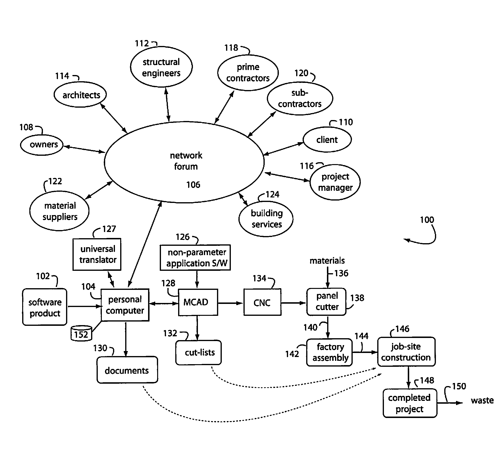
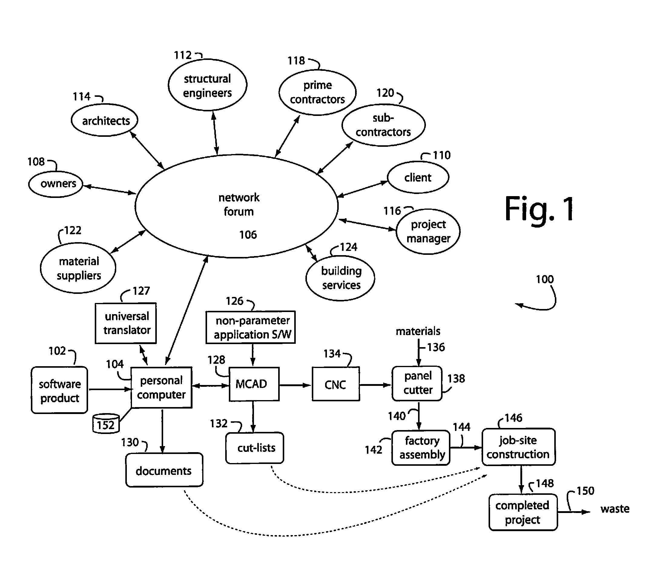
[0024]FIG. 1 represents a building design and construction system embodiment of the present invention, and is referred to herein by the general reference numeral 100. System 100 comprises software and hardware components that attach to an otherwise standard computer system running mechanical CAD software application programs. A software product 102 purchased by the user is loaded on a personal computer 104. The executed program erects a network forum 106 through a network adapter and Internet connection. The network forum 106 provides an interactive and simultaneous mechanism for several project contributors, e.g., owners 108, clients 110, structural engineers 112, architects 114, project managers 116, prime contractors 118, sub-contractors 120, material suppliers 122, and building services 124 to cooperatively carry out a project from concept to completion on-line using three-dimensional modeling.

[0025]A universal translator 127 is employed that allows the several contributors in t...


PUM


Abstract

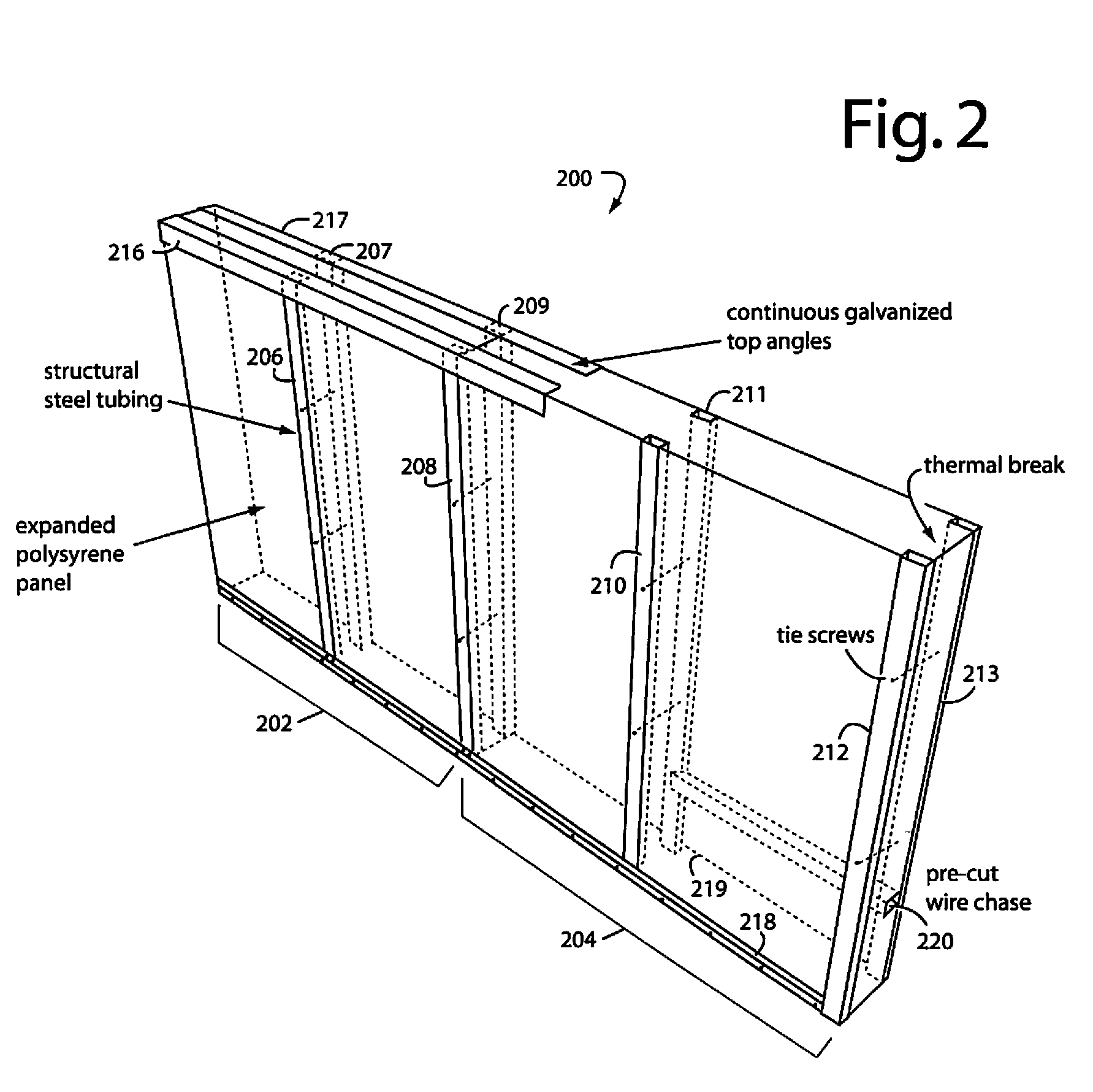
A method of building construction includes designing a building with software for execution on a computer such that an envelope of the building principally comprises expanded polystyrene foam panels, and the software is used to automatically generate a plan with reference numbers that identify substantially all the component pieces of the building. The software and computer are coupled to a computer aided design (CAD) program for generating computer numerical controlled (CNC) milling commands for expanded polystyrene foam panels, and a cut-list for steel reinforcing studs to fit into matching slots milled into the expanded polystyrene foam panels. At least the expanded polystyrene foam panels and matching steel reinforcing studs are marked with identifying numbers corresponding to the reference numbers. The expanded polystyrene foam panels are milled with a CNC machine and panel cutter according to CNC milling commands from the CAD program.

Description

BACKGROUND OF THE INVENTION[0001]1. Field of the Invention[0002]The present invention relates to construction and design tools, and in particular to computer programs and systems for designing buildings, generating accurate cut-lists, cutting and assembling materials, and reducing environmental waste.[0003]2. Description of the Prior Art[0004]The process of building construction has conventionally been a single file march of developers, architects, engineers, government, contractors, and material suppliers that operate in a sequential then pseudo collaborative fashion. This siloed, head-to-toe approach often leads to inefficiencies. Rough plans, with the details left open, lead to various interpretations, on-site decision making, and wasteful construction that is not environmentally friendly. It also limits the ability to optimize building scale and timing. Very often persons involved face unexpected results, and exceed costs. Conventional building methods commonly include miscommun...

Claims


Application Information

Patent Timeline
Patent Type & Authority Patents(United States)
IPC IPC(8): G06F19/00G05B19/18G06F17/50
CPCG05B19/4097G06F17/5004G06F30/13
Inventor HEIL, DUANE A.
Owner COMPASS PROPERTY GRP
Learn More