
Portable power source and portable power source system

a power source and portable technology, applied in the direction of cell components, final product manufacturing, sustainable manufacturing/processing, etc., can solve the problems of battery performance impairment, lithium ion secondary batteries, heavy weight of batteries, etc., and achieve the effect of reducing the manufacturing cost of battery packs

Inactive Publication Date: 2012-06-19
GK BRIDGE 1
View PDF12 Cites 0 Cited by
  • Summary
  • Abstract
  • Description
  • Claims
  • Application Information

AI Technical Summary

Benefits of technology

Prevents short circuits and ensures appropriate charging / discharging conditions, enhancing battery safety and performance by requiring specific operations for terminal connection and shielding internal terminals from accidental contact.

Problems solved by technology

Although nickel-cadmium batteries, nickel-metal hydride batteries and the like are mainly used as the power sources for equipment such as electric tools that have been adapted to use in cordless applications, these batteries have a heavy weight, and therefore the use of lithium ion secondary batteries, which are lightweight, has been attempted lately.
Lithium ion secondary batteries, however, may not be able to maintain the battery performance such as the cycle life if the charge / discharge conditions are not controlled appropriately.
When they are discharged under a special condition, including, for example, a case in which the positive terminal and the negative terminal are short-circuited, the battery performance may be significantly impaired.
However, a pair of connection terminals included in the battery pack is often exposed to the outside.
Due to such external factors, there is the possibility that short circuit may occur between the terminals of the battery pack.
Also in such a case, the charge conditions cannot be controlled appropriately, so that there is the possibility that the battery performance may be significantly impaired.
In this case, short circuit will not occur unless lead wires or the like are intentionally connected to the terminals; however, short circuit or the like cannot be sufficiently prevented since the terminals are exposed in a state where the cover is released.
However, by simply inserting off-specification lead wires or the like into external terminal inserting portions, the lead wires or the like can be connected to the terminals, so that the possibility of charging / discharging of the battery under inappropriate conditions has not been totally eliminated.

Method used


Image

  • Portable power source and portable power source system
  • Portable power source and portable power source system
  • Portable power source and portable power source system

Examples


Embodiment Construction

[0038]In this embodiment, a description is given, with reference to the drawings, of a portable power source and a portable power source system that have a double action system in which a first operation of inserting external terminals into external terminal inserting portions of a battery pack is performed, and thereafter a second operation of rotation about the inserting direction as the rotation axis is performed.

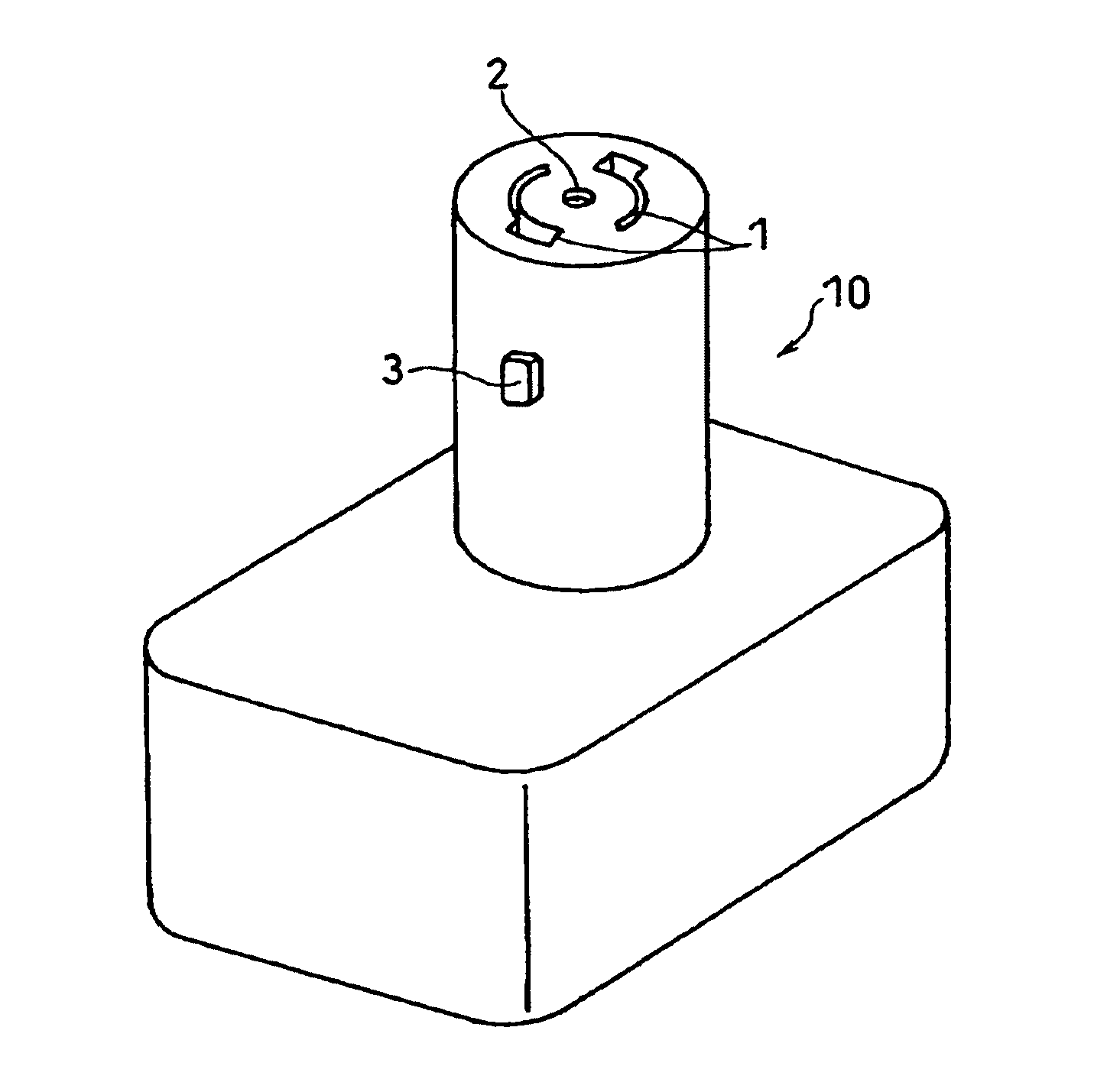
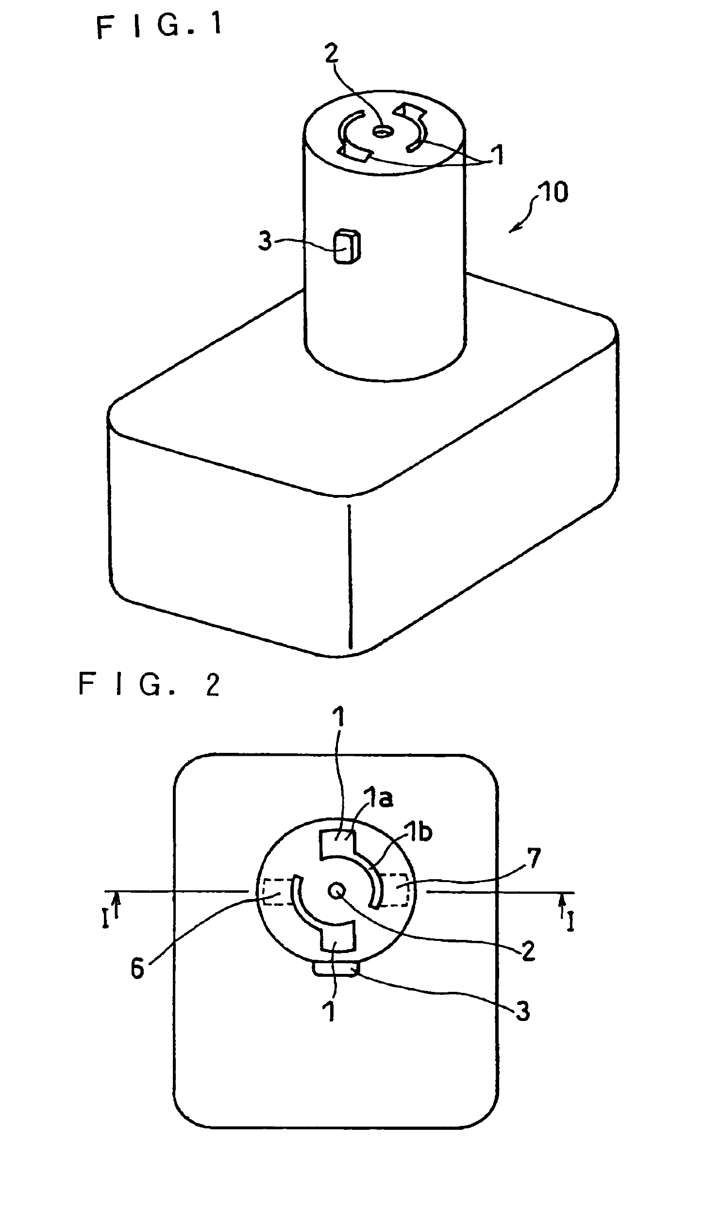
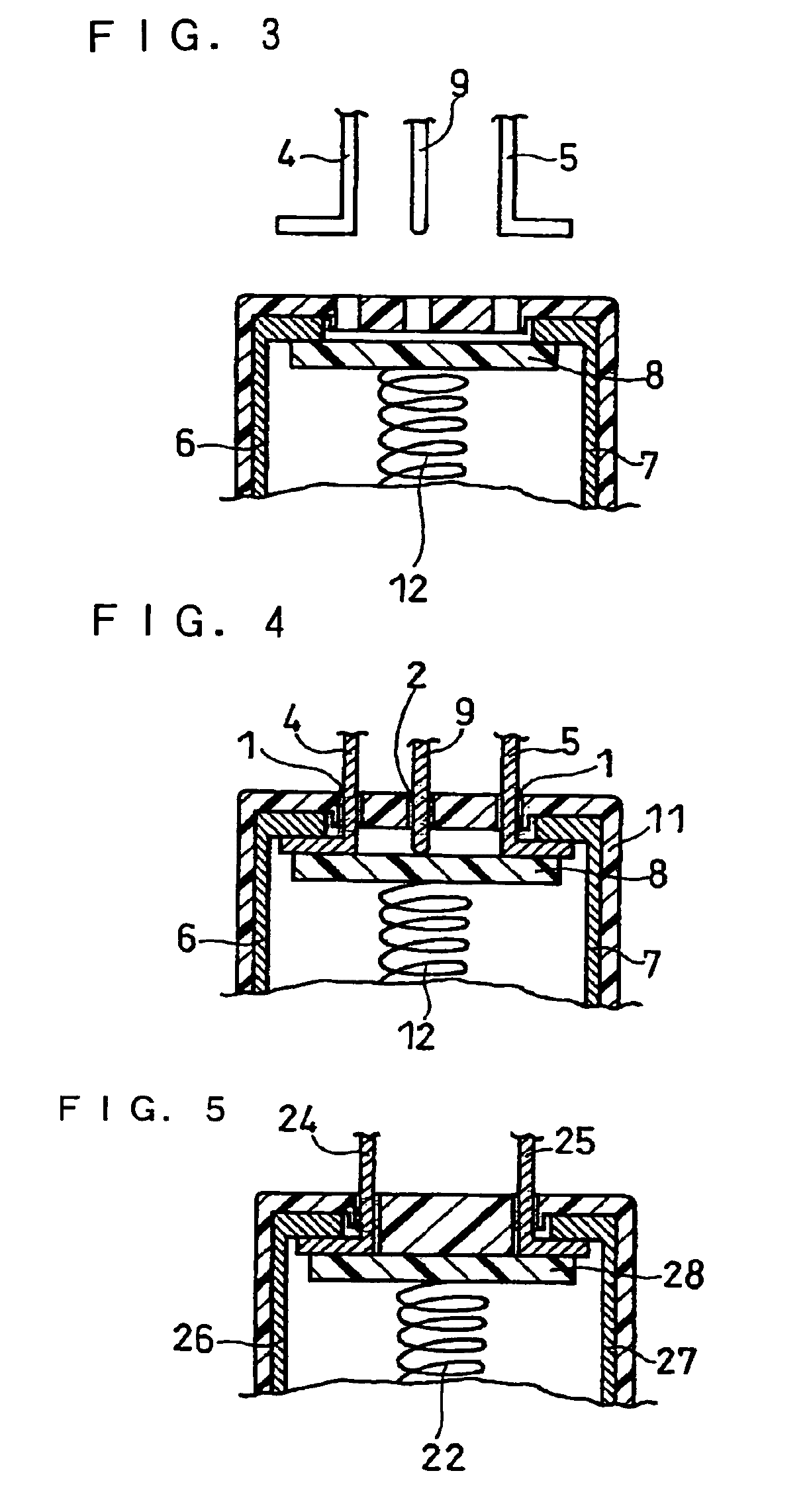
[0039]FIG. 1 is a perspective view of a battery pack 10 according to this embodiment, and FIG. 2 is a top view thereof. FIG. 3 and FIG. 4 are cross-sectional views of relevant parts of the battery pack 10 according to this embodiment, respectively showing an unconnected state and a connected state between a pair of external terminals 4 and 5 and a first internal terminal 6 and a second internal terminal 7 of the battery pack. FIG. 4 corresponds to a relevant part of a cross-sectional view taken on the line I-I in FIG. 2. In this embodiment, the battery pack 10 per se con...


PUM

PropertyMeasurementUnit
discharge voltageaaaaaaaaaa
chargeaaaaaaaaaa
rotationaaaaaaaaaa

Abstract

A portable power source system including a battery pack housing at least one secondary battery, wherein first and second internal terminals for connecting to a pair of external terminals are provided inside the battery pack, and two or more operations in different operating directions are required to connect the external terminals to the internal terminals. The battery pack includes external terminal inserting portions for inserting the external terminals, and the two or more operations include a first operation including inserting the external terminals into the external terminal inserting portions and a second operation in a direction different from that of the first operation. In a state before the first operation is performed, at least one of the internal terminals is shielded with a protective cover, and the protective cover recedes from a position for shielding the internal terminal, in conjunction with the first operation, the second operation or a combination of the first operation and the second operation, thereby enabling a connection of the external terminals to the internal terminals.

Description

RELATED APPLICATIONS[0001]This application a Divisional of U.S. application Ser. No. 10 / 558,675, filed Nov. 30, 2005, which is the U.S. National Phase under 35 U.S.C. §371 of International Application No. PCT / JP2005 / 000010, filed Jan. 5, 2005, which in turn claims the benefit of Japanese Application No. 2004-007701, filed Jan. 15, 2004, the entire contents of each of which are hereby incorporated by reference.TECHNICAL FIELD[0002]The present invention relates to a portable power source and a portable power source system that include a battery pack, and more particularly to a terminal structure of a battery pack.BACKGROUND ART[0003]Recently, cordless or portable applications have been increasingly realized also for equipment such as electric tools, and there is an increasing demand for portable power source systems. While electric tools such as an electric screwdriver are widely used for business purposes in construction sites and the like since they can dramatically improve working ...

Claims


Application Information

Patent Timeline
Patent Type & Authority Patents(United States)
IPC IPC(8): H01M6/00H01M2/00H01M10/00H01M10/38H01M50/529B25F5/00H01M10/46H01M50/244H01M50/296H01M50/591
CPCB25F5/00H01M2/06H01M2/34H01M2/1022H01M10/46Y02E60/10Y02P70/50H01M50/591H01M50/296H01M50/244
Inventor SHIRANE, TAKAYUKI
Owner GK BRIDGE 1
Learn More