
Engine room for construction equipment

a construction equipment and engine room technology, applied in the field of engine room for construction equipment, can solve the problems of increased manufacturing cost, inability to solve the basic noise problem, and inability to effectively eliminate the noise of the engine room, so as to reduce the noise emission, prevent the overheating of the corresponding components, and low cost

Inactive Publication Date: 2012-06-12
VOLVO CONSTR EQUIP HLDG SWEDEN AB
View PDF28 Cites 138 Cited by
  • Summary
  • Abstract
  • Description
  • Claims
  • Application Information

AI Technical Summary

Benefits of technology

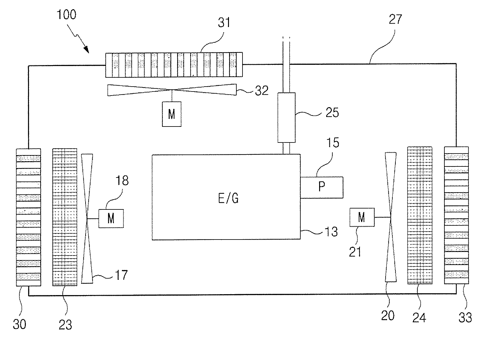
[0016]An embodiment of the present invention relates to an engine room for construction equipment, which can reduce emission of noise generated in an engine room due to driving of an engine and a ventilating fan to an outside of the engine room by absorbing the noise through a noise trap, and can prevent corresponding components from overheating by smoothing inhalation / discharge of an external air to / from the airtight engine room.
[0017]An embodiment of the present invention relates to an engine room for construction equipment, which can solve conflicting technical problems to make an engine room airtight for noise reduction caused by engine driving and to circulate an external air through openings for cooling of heat-generating components in the engine room at low cost.

Problems solved by technology

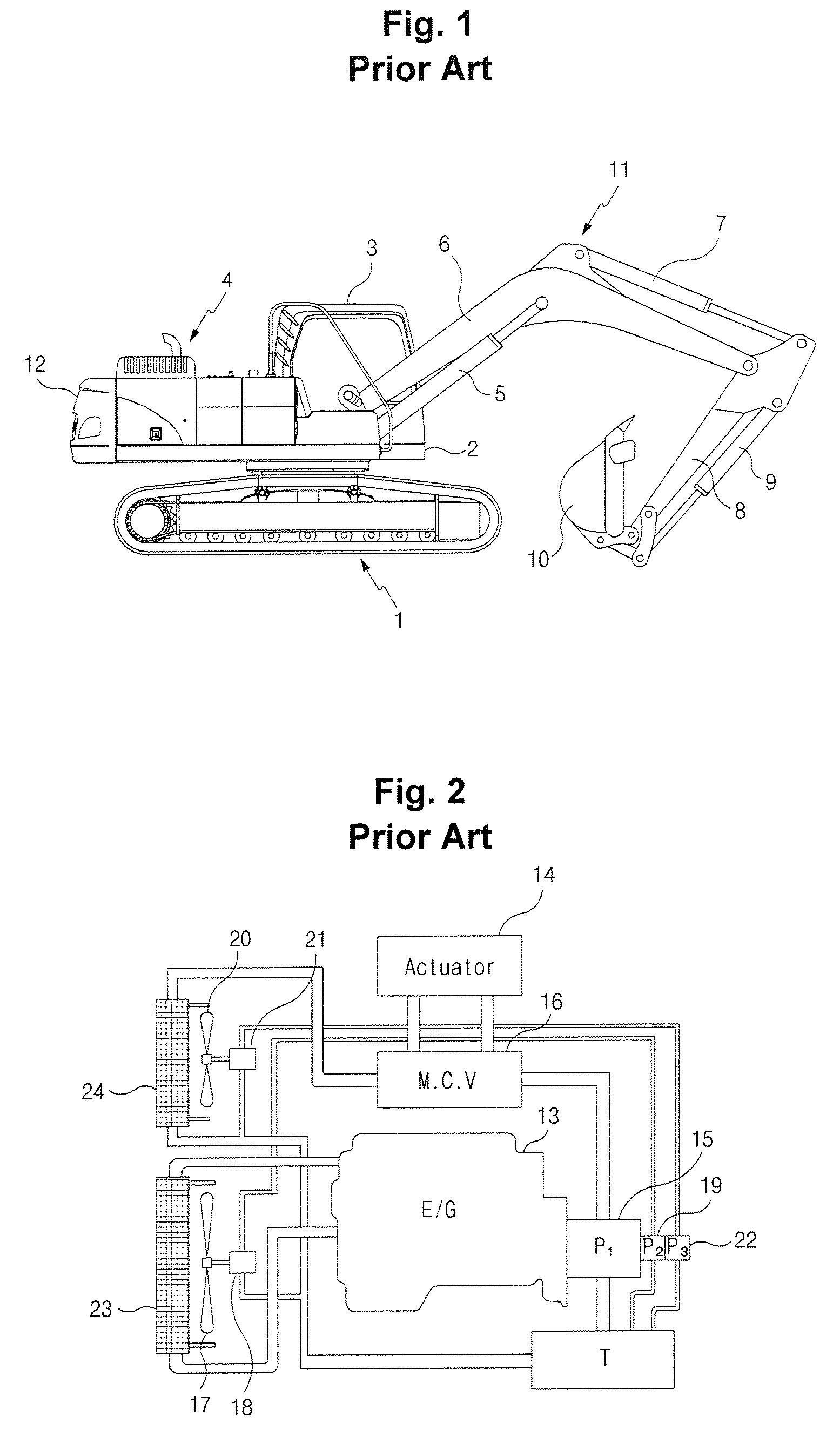
Accordingly, due to high heat generated in the engine room, a sound-absorbing material and so on installed in the engine room may catch fire.
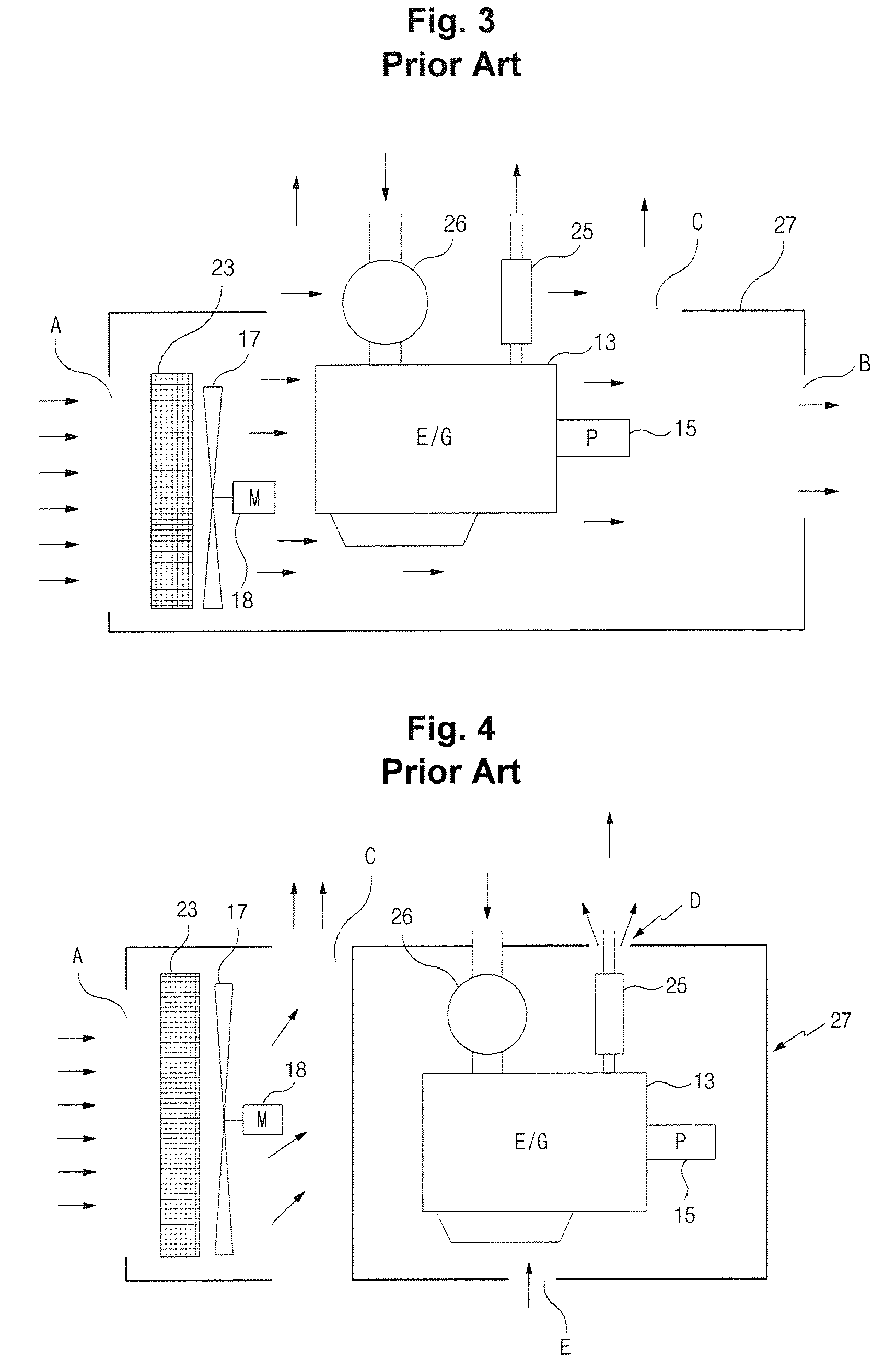
In addition, even in the case of making the engine room airtight due to the noise generated during operation of the radiator fan 17, the noise problem cannot be basically solved.
The enlarged radiator fan 17 occupies much space in the engine room, and causes the manufacturing cost to be increased.

Method used


Image

  • Engine room for construction equipment
  • Engine room for construction equipment
  • Engine room for construction equipment

Examples


Embodiment Construction

[0033]Hereinafter, preferred embodiments of the present invention will be described with reference to the accompanying drawings. The matters defined in the description, such as the detailed construction and elements, are nothing but specific details provided to assist those of ordinary skill in the art in a comprehensive understanding of the invention, and thus the present invention is not limited thereto.

[0034]As illustrated in FIG. 5, an engine room for construction equipment having an engine, a hydraulic pump connected to the engine, an inlet port inhaling an external air into an engine room, and an outlet port discharging the air in the engine room to an outside, includes a radiator 23 cooling water for cooling the engine 13; a muffler 25 discharging an exhaust gas from the engine 13 to the atmosphere; a first noise trap (which is used for the purpose of permitting air flow, absorbing noise generated in the engine room 100, and interfering with the air flow to intercept noise em...


PUM


Abstract

An engine room for construction equipment is provided, which can minimize emission of noise generated in an engine room due to driving of an engine and a ventilating fan to an outside of the engine room by absorbing the noise through a noise trap, and can improve the cooling performance of corresponding components by smoothing inhalation / discharge of an external air to / from the airtight engine room. The engine room for construction equipment includes a radiator cooling water for cooling the engine, a muffler discharging an exhaust gas from an engine to the atmosphere, a first noise trap installed in an inlet port to absorb noise generated in the engine room and emitted to an outside, a second noise trap installed in an outlet port to absorb the noise generated in the engine room and emitted to the outside, a radiator fan inhaling the external air through the first noise trap and making the inhaled external air pass through the radiator and the circumference of the engine, a discharge fan discharging the air in the engine room to the outside through the second noise trap, and an outer wall forming an airtight space for accommodating therein the engine, the muffler, the radiator fan, the hydraulic pump, and the discharge fan that generate the noise.

Description

CROSS-REFERENCE TO RELATED APPLICATION[0001]This application is based on and claims priority from Korean Patent Application No. 10-2008-0024772, filed on Mar. 18, 2008 in the Korean Intellectual Property Office, the disclosure of which is incorporated herein in its entirety by reference.BACKGROUND OF THE INVENTION[0002]1. Field of the Invention[0003]The present invention relates to an engine room for construction equipment, which can minimize emission of noise generated in an engine room of an excavator and so on to an outside of the engine room.[0004]More particularly, the present invention relates to an engine room for construction equipment, which can minimize emission of noise generated in an engine room due to driving of an engine and a ventilating fan to an outside of the engine room by absorbing the noise through a noise trap, and can improve the cooling performance of corresponding components by smoothing inhalation / discharge of an external air to / from the airtight engine ro...

Claims


Application Information

Patent Timeline
Patent Type & Authority Patents(United States)
IPC IPC(8): F02B77/13F01P7/10B60K11/04E02F9/00F01P5/06
CPCE02F9/0866E02F9/00E02F9/08E02F3/00
Inventor IKEDA, TOSHIMICHICHO, GYENG SOOYUK, WOOK SUNG
Owner VOLVO CONSTR EQUIP HLDG SWEDEN AB
Learn More