Non-contact optical coherence tomography imaging of the central and peripheral retina

a technology of optical coherence tomography and peripheral retina, which is applied in the field of non-contact optical coherence tomography (oct) imaging of the central and peripheral retina, can solve the problem that no information can be obtained from the vitreoretinal interface, and achieve the effect of eliminating facilitating the examination of patients, and reducing the time spent on dilation

Inactive Publication Date: 2012-06-05
PEYMAN GHOLAM A
View PDF4 Cites 0 Cited by
  • Summary
  • Abstract
  • Description
  • Claims
  • Application Information

AI Technical Summary

Benefits of technology

[0014]This invention can provide access to the retinal periphery and simplifies taking images. These sections of the retinal periphery may provide important information about the diseased areas of the peripheral retina permitting evaluation and potential treatment. Additionally, the present invention enables ophthalmologists to visualize and diagnose a variety of ailments including glaucoma, macular degeneration, retinal detachment, and diabetic retinopathy and all peripheral retinal diseases. The OCT system of the present invention can utilize low coherent visible or preferably infra red wave lengths of up to 10640 nm. The OCT system of the present invention can also makes a patient's examination easier by eliminating the time spent to dilate the patients pupil and reducing the focusing time, which improves the patient's tolerance of the procedure since a wide-field fundus photograph can be generated with the same infrared light without blinding the patient with visible light.

Problems solved by technology

In conventional systems no information can be obtained from the vitreoretinal interface in the retinal periphery which is main cause of retinal tear and retinal detachment which is one of the main cause of blindness more frequently in near sighted patients.

Method used


Image

  • Non-contact optical coherence tomography imaging of the central and peripheral retina
  • Non-contact optical coherence tomography imaging of the central and peripheral retina
  • Non-contact optical coherence tomography imaging of the central and peripheral retina

Examples


Embodiment Construction

[0022]Embodiments of the present invention may include imaging modalities, such as optical coherence tomography, snapshot imaging Polarimetry and computed tomography imaging spectrometer. Additionally, White Light LED, infra red diodes, Nd—YAG as an illumination source, can each maintain excellent image quality across the field of view.

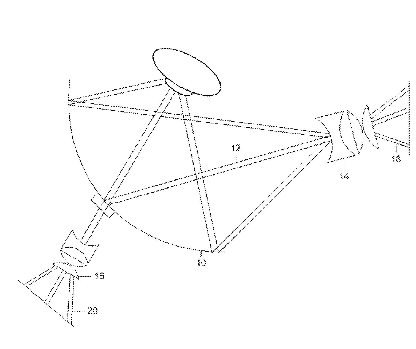
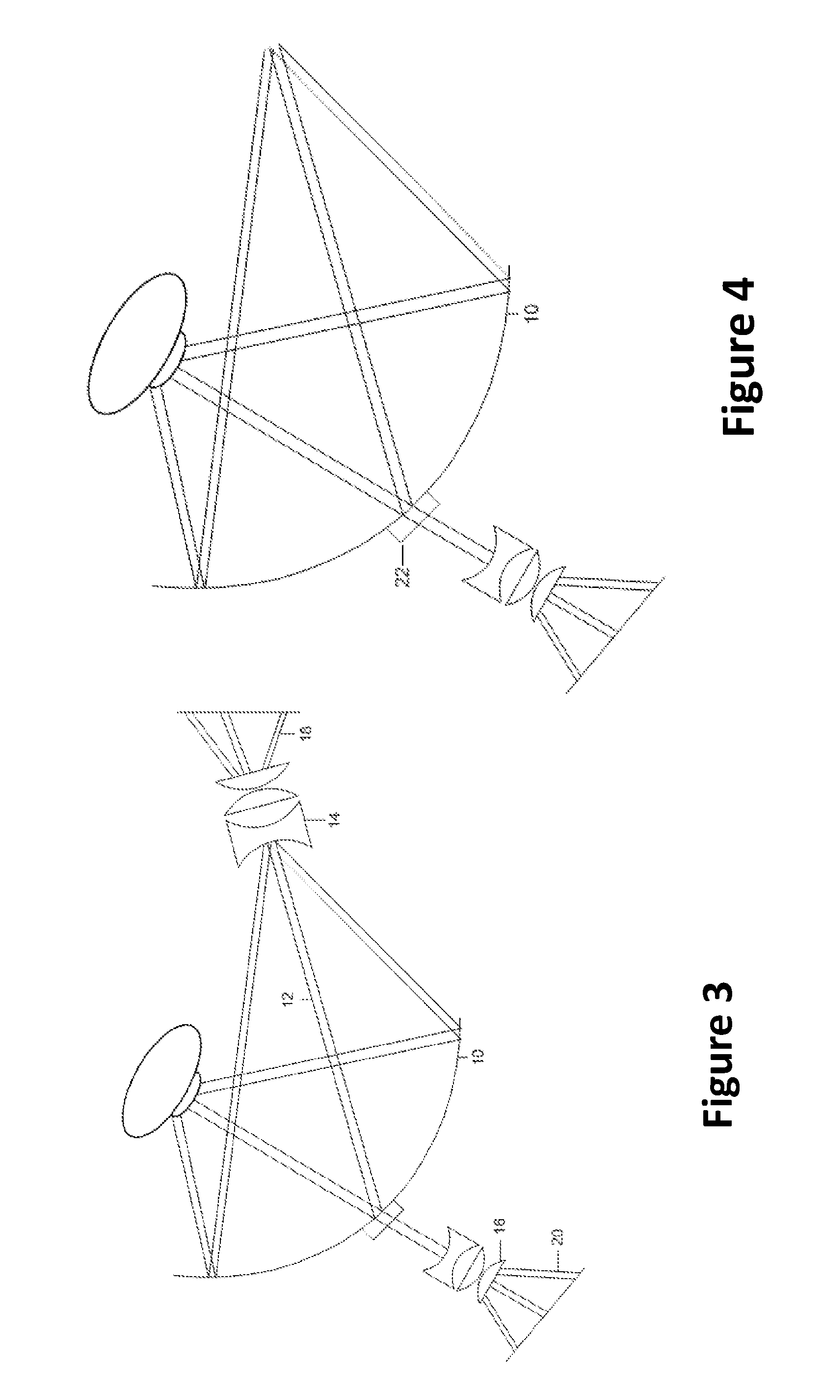
[0023]Spectral Domain Optical Coherence Tomography, OCT, operates in substantially the same manner as a low coherence Michelson interferometer. That is, light from a broadband source is separated into a reference and sample arm. Reflected light from both arms is recombined in the detection arm to form interference fringes when the optical path difference between sample and reference arms is within the coherence length of the source. The signal produced by the detection of interference fringes is proportional to the backscatter from the depth structure of the sample. Spectral components of the light in the detector arm are separated by a spectrometer a...


PUM


Abstract

A system includes a mirror having an axis extending through a central portion thereof, and a portion of the mirror being configured to repeatedly oscillate between a first position and a second position around the axis, so as to record a field of up to 200 degrees of a portion of the central and peripheral retina, a first scanner configured to use a spectral domain optical coherence tomography system to obtain a non-contact wide angle optical coherence tomography-image of the portion of the central and peripheral retina, and a second scanner configured to obtain an image of the retina, wherein the mirror is configured to oscillate so as to move the focal point of the mirror from one side of a pupil to another side, thereby permitting scanning light inside the eye to cover a predetermined peripheral field, thus creating a two dimensional or three dimensional image of the field.

Description

CROSS REFERENCE TO RELATED APPLICATION[0001]This application is a continuation-in-part of U.S. application Ser. No. 12 / 492,491, filed Jun. 26, 2009, now U.S. Pat. No. 8,070,289 the entirety of which is incorporated herein by reference.BACKGROUND[0002]1. Field of Invention[0003]The present invention relation to a system for Non-contact Optical Coherence Tomography (OCT) imaging of the central and peripheral retina.[0004]2. Related Art[0005]Ophthalmic Optical Coherence Tomography (OCT) of the eye was originally developed by obtaining cross-sectional images of the sensory retina and retinal pigment epithelium. Recently, spectral domain OCT became available, a new technique that allowed major improvements particularly regarding image acquisition speed and image resolution. However, existing instruments do not scan the retinal periphery. The OCT scan is typically restricted to the central <40° of the retina.[0006]OCT is presently used (in ophthalmology) to evaluate only either the thi...

Claims


Application Information

Patent Timeline
Patent Type & Authority Patents(United States)
IPC IPC(8): A61B3/14A61B3/10
CPCA61B3/102A61B3/1225A61B5/0066A61B3/14
Inventor PEYMAN, GHOLAM A.
Owner PEYMAN GHOLAM A
Why Eureka
Try Eureka