
Light guide plate and side-emitting backlight module having the same

a technology of side-emitting backlight and guide plate, which is applied in the direction of fixed installation, lighting and heating apparatus, instruments, etc., can solve the problems of indirect reduction of yield rate and light use efficiency, increase cost, etc., and achieve the effect of improving light use efficiency, improving optics distribution and light gathering

Active Publication Date: 2012-05-29
NANO PRECISION TAIWAN LTD
View PDF6 Cites 12 Cited by
  • Summary
  • Abstract
  • Description
  • Claims
  • Application Information

AI Technical Summary

Benefits of technology

[0009]The present invention is to provide a light guide plate with a micro-structure, applied in the backlight module to improve the optics distribution and light gathering, also to increase the light use efficiency and adjust the optics display.

Problems solved by technology

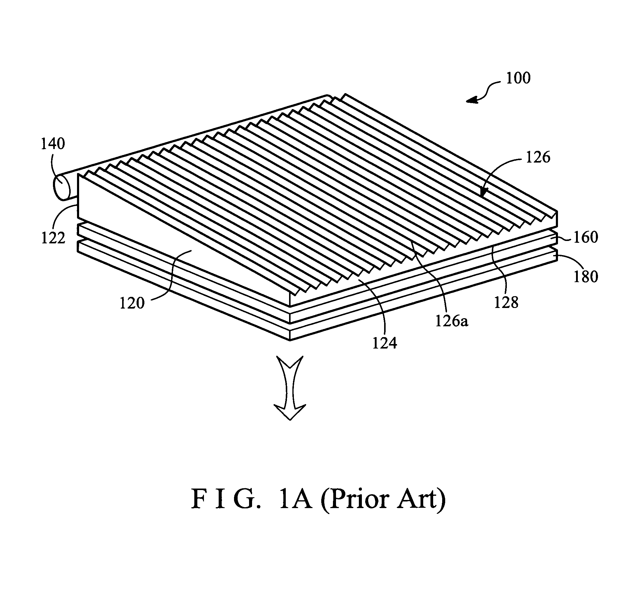
For the above issues, the conventional method is to fabricate the thick end-surface 122 into a fogging surface which makes the light inside the light guide plate 120 scattered, but it adds fabrication steps, increases cost and thus reduces yield rate indirectly as well as the light use efficiency.

Method used


Image

  • Light guide plate and side-emitting backlight module having the same
  • Light guide plate and side-emitting backlight module having the same
  • Light guide plate and side-emitting backlight module having the same

Examples


Embodiment Construction

[0025]In the following detailed description of the preferred embodiments, reference is made to the accompanying drawings which form a part hereof, and in which are shown by way of illustration specific embodiments in which the invention may be practiced. In this regard, directional terminology, such as “top,”“bottom,”“front,”“back,” etc., is used with reference to the orientation of the Figure(s) being described. The components of the present invention can be positioned in a number of different orientations. As such, the directional terminology is used for purposes of illustration and is in no way limiting. On the other hand, the drawings are only schematic and the sizes of components may be exaggerated for clarity. It is to be understood that other embodiments may be utilized and structural changes may be made without departing from the scope of the present invention. Also, it is to be understood that the phraseology and terminology used herein are for the purpose of description an...


PUM


Abstract

A light guide plate and a side-emitting backlight module having the same are disclosed. The light guide plate includes a transparent substrate, a plurality of prisms and a plurality of condensing lenses. The prisms are arranged side by side on one surface of the transparent substrate. The condensing lenses are disposed between two adjacent prisms, and distributed from sparsely to densely along a direction of a crest line of each of the prisms.

Description

BACKGROUND OF THE INVENTION[0001](1) Field of the Invention[0002]The present invention relates to a light guide plate and a side-emitting backlight module having the same, and more particularly relates to a light guide plate with a micro-structure and a side-emitting backlight module having the same.[0003](2) Description of the Prior Art[0004]A light guide plate is an important component affecting the light efficiency of a side-emitting backlight module. The light guide plate is applied to the side-emitting backlight module to transform the light beam from a point light or a line light source to an uniform plane light and then enhance the uniformity and brightness of the plane light based on the light uniform ability of a diffusion film and light concentration ability of a brightness enhancement film. The light guide plate has two types of appearance, wedge and flat. Generally, a notebook computer adopts wedge type due to considering the space allocation, while a liquid crystal disp...

Claims


Application Information

Patent Timeline
Patent Type & Authority Patents(United States)
IPC IPC(8): F21V7/04
CPCG02B6/0036G02B6/0038G02B6/0061
Inventor CHEN, CHIEN-HSIANGLIU, MING-DAH
Owner NANO PRECISION TAIWAN LTD
Learn More