
Air-bearing slider design for sub-nanometer clearance in hard disk drive (HDD)

a technology of sub-nanometer clearance and hard disk drive, which is applied in the direction of recording head housing/shield, record information storage, instruments, etc., can solve the problems of head failure, difficult to find an appropriate design of the air-bearing surface, and destabilizing the slider, etc., to reduce the sensitivity to crown, psa and z-height variations, and improve the effect of airflow and pressure distribution

Active Publication Date: 2012-05-22
HEADWAY TECH INC +1
View PDF11 Cites 21 Cited by
  • Summary
  • Abstract
  • Description
  • Claims
  • Application Information

AI Technical Summary

Benefits of technology

[0015]The first is to provide a slider with an air-bearing surface (ABS) design that will aid in relieving sub-nanometer clearance problems in a HDD.
[0016]A second object of the present invention is to provide such an ABS design that will also eliminate problems associated with compression shock that are most commonly addressed by suspension design rather than ABS design.
[0017]A third object of the present invention is to provide such an ABS design that will provide an elimination of problems associated with backflow and lubricant accumulation.
[0018]A fourth object of the present invention is to provide a slider ABS design that will reduce sensitivity to crown, PSA and Z-height variations.
[0019]A fifth object of the present invention is to provide an ABS design that will provide a high damping coefficient so that the slider quickly reverts to a stable aerodynamic condition subsequent to an inadvertent head / disk interaction.
[0020]These objects will be achieved by a slider having an ABS topography in which a variable depth pattern of grooves and channels achieves a particularly advantageous airflow and pressure distribution (as will be described in greater detail below). First, a transverse (to a central axis) deep air groove is bisected longitudinally (along the central axis) by an asymmetric (in height) two-rail “dual-height bridge,” so that skew effects and track-uniformity as a function of altitude are addressed. Next, a T-shaped configuration formed by two abutting channels, one longitudinal and one transverse, accumulates and directs airflow from the slider LE to a center pad at the TE, within which the transducer is embedded, even at the lowered pressures of high altitudes. A junction between the two segments of the T allows improvement of performance under compression shocks, without the necessity of utilizing the properties of the suspension. Adjusting the depths of these channels according to the performance characteristics of the HDD allows the building up of pressure on the center pad, thereby enhancing pitch and roll stiffness. Next, the disturbed airflow patterns beneath the flying slider produces high damping coefficients of pitch and roll modes at the natural frequencies of the air-bearing system. In addition, a shallow dam at the TE of the slider serves as a load / unload support mechanism and backflow blocker, which provides resistance to head / disk contacts during operation and reduces the accumulation of lubricant that would normally be picked up by the backflow.

Problems solved by technology

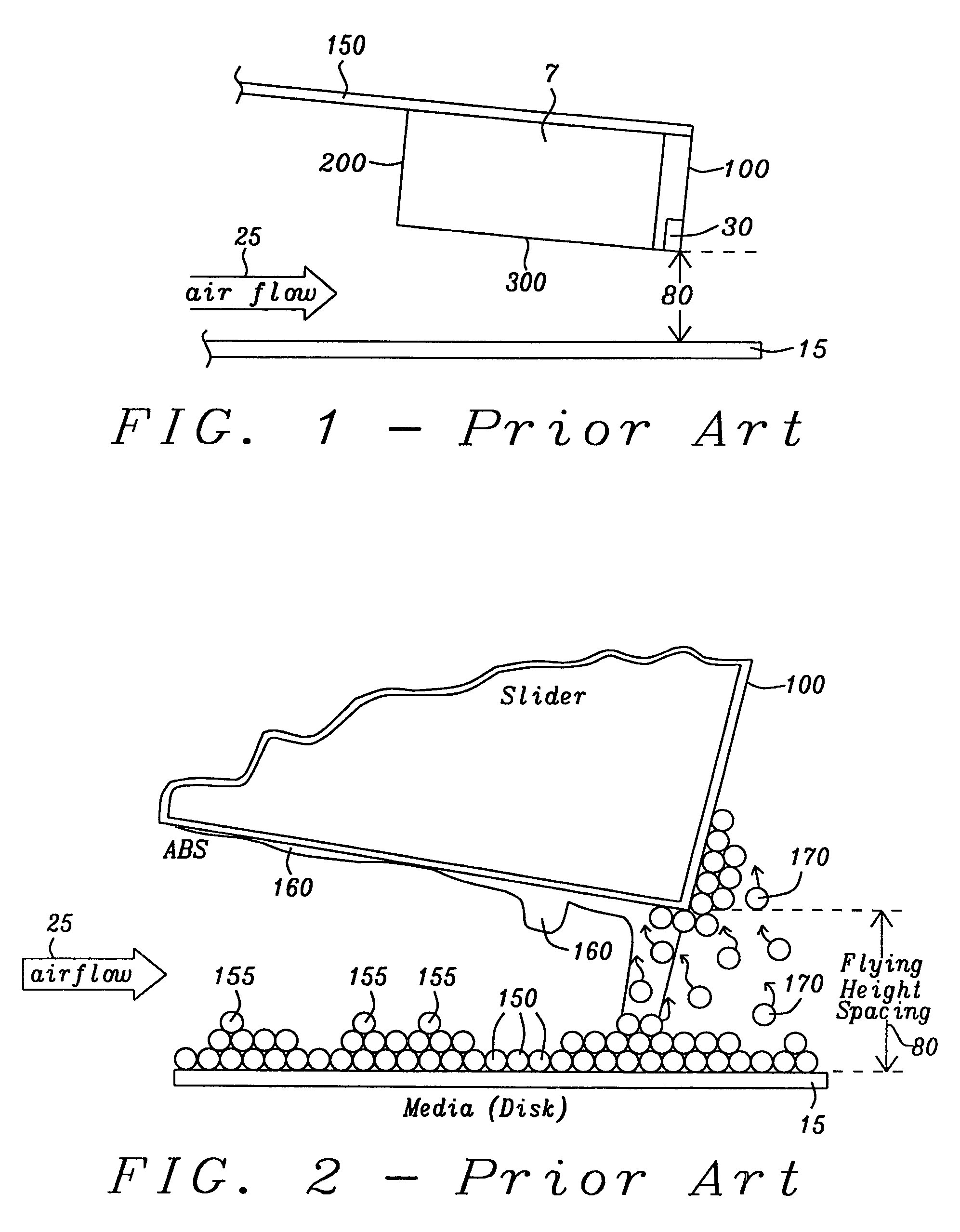
Under conditions of such low clearance, a variety of proximity interactions, such as intermolecular forces (IMF), meniscus and electrostatic forces (ESF) as well as the influence of disk topography, tend to destabilize the air-bearing slider.
It has proven to be very difficult to find an appropriate design of the air-bearing surface (ABS) of a slider that will enable it to fulfill the stability requirements of current operational conditions.
In other words, the anti-liftoff is usually much better than anti-compression and, as a result, heads now tend to fail as a result of compression shock, given the sub-nanometer clearance of current operational conditions.
As a result, the read / write clearance cannot stabilize because the accumulating lubricant on the ABS affects the aerodynamics of the slider and further affects its stability and the reliability of the HDD.

Method used


Image

  • Air-bearing slider design for sub-nanometer clearance in hard disk drive (HDD)
  • Air-bearing slider design for sub-nanometer clearance in hard disk drive (HDD)
  • Air-bearing slider design for sub-nanometer clearance in hard disk drive (HDD)

Examples


Embodiment Construction

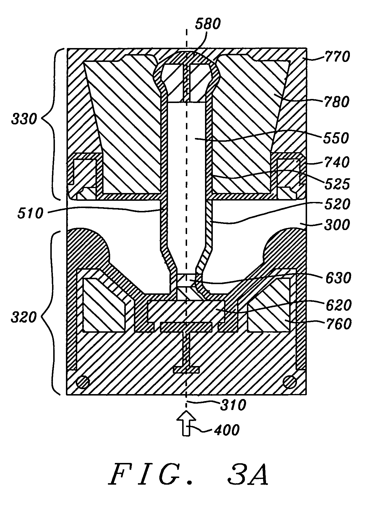
[0033]The preferred embodiment of the present invention is an aerodynamically stable slider, preferably designed in the form of the slider illustrated in FIGS. 3A, and 3B. This slider has an ABS topography that eliminates a variety of problems associated with sub-nanometer flying heights and meets the objects set forth above.

[0034]Referring now to FIGS. 3A, 3B and 3C there is shown, first in FIG. 3A, an underside ABS planar view of a preferred embodiment of the slider of the present invention. For purposes of clarity in the illustration, progressively lighter (less line density) shaded areas represent surface areas of greater depth relative to an uppermost plane of the slider ABS.

[0035]Next, in FIG. 3B, there is a 3-dimensional perspective illustration showing an alternative view of the slider in FIG. 3A. This view is presented solely for the purpose of visually clarifying the topography illustrated in the shaded planar view of FIG. 3A, it is not meant to indicate actual depths inci...


PUM


Abstract

A slider is formed by a three-step ion milling process with an ABS topography that provides aerodynamic stability at sub-nanometer flying heights. The ABS design significantly eliminates the accumulation of lubricant and removes whatever lubricant does accumulate by use of a shallow dam at the trailing edge. In addition, a junction between a down-track channel and a cross-track channel directs airflow towards a center pad in which a transducer is embedded so that the pressure at the pad is enhanced even under high altitude conditions. The slider ABS is divided into two portions by a transverse deep air channel, but the channel is bridged by the cross-track channel which crosses the deep air channel with sides of unequal height. This dual height bridge allows variations in skew angle to be compensated so that pressure variations across the disk tracks are significantly reduced.

Description

BACKGROUND OF THE INVENTION[0001]1. Field of the Invention[0002]This invention relates to the fabrication of slider-mounted thin film magnetic read / write heads and particularly to a method for forming a slider air bearing surface (ABS) suitable for sub-nanometer clearances.[0003]2. Description of the Related Art[0004]In magnetic hard disk drives (HDD) the data on a disk is recorded and retrieved by a transducer (or “element”). Each magnetic head element is embedded within a slider which is in aerodynamic flight over a rotating disk at a height (flying height) of 10 nm or less. Other than passive fly height (fly height without active operator intervention), the active spacing during read / write is actually becoming even less, perhaps as low as 2 nm, in order to achieve higher areal density and disk capacity. For example, so-called fly on demand (FOD) or dynamic fly height (DFH) is now applied to control magnetic spacing via the protrusion of an element / transducer caused by the thermal...

Claims


Application Information

Patent Timeline
IPC IPC(8): G11B5/55
CPCG11B5/102G11B5/6082
Inventor ZHENG, GUOQIANGCHA, ELLISFENG, ZHUYEUNG, SINDY
Owner HEADWAY TECH INC
Learn More