
System and method for performing thermal analysis on a building through universal meshing

a technology of universal meshing and thermal analysis, applied in the field offinite element analysis, to achieve the effect of reducing time, effort and expense, and high thermal conductivity valu

Inactive Publication Date: 2012-05-15
OWENS CORNING INTELLECTUAL CAPITAL LLC
View PDF7 Cites 0 Cited by
  • Summary
  • Abstract
  • Description
  • Claims
  • Application Information

AI Technical Summary

Benefits of technology

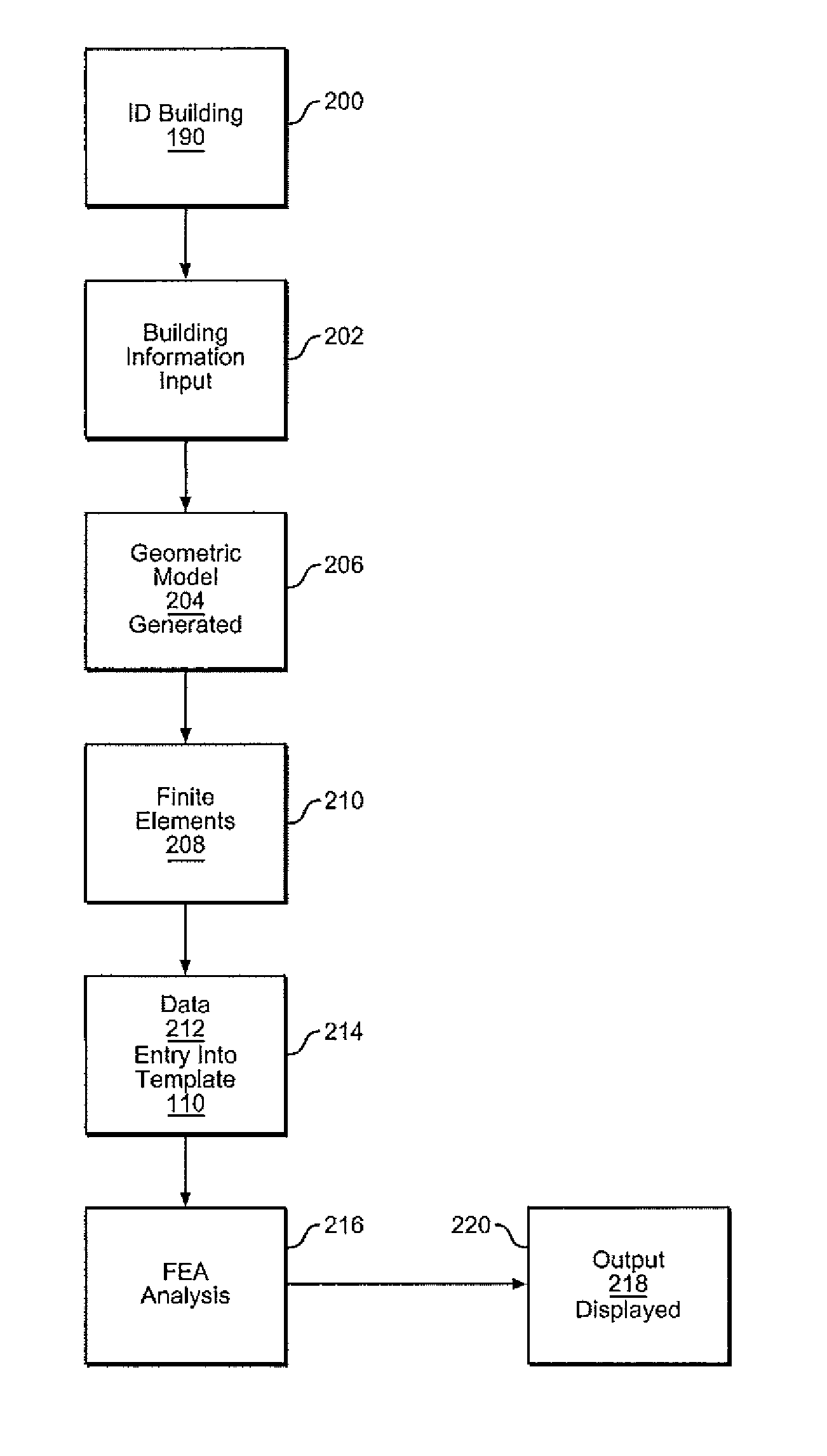
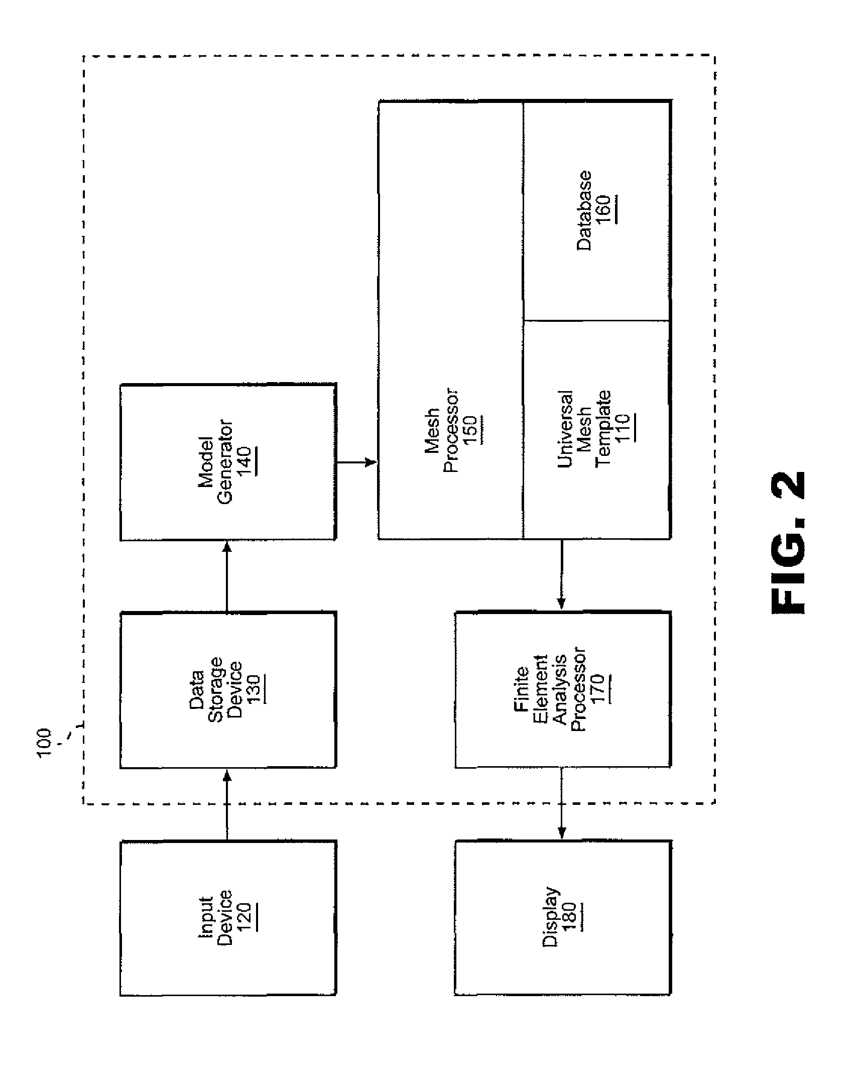
[0005]The present invention is directed to generating a building insulation model with a universal mesh from a template representing the entire range of potential insulation profiles, with the mesh being used for conducting one, two or three-dimensional finite element analysis (FEA). The system and method take into account a wide range of heat related factors, including structural materials of the building, insulation components encompassing both insulation materials employed in the building process and established air pockets or gaps, and even fasteners used in the construction process. Pre-established layers in the universal mesh which do not directly correspond to existing insulation components are automatically assigned a very high thermal conductivity value so as to be negligible in the overall insulation analysis. The overall system significantly reduces the time, effort and expense required for creating a computational mesh for modeling heat transfer in building insulation assemblies, particularly metal buildings. Further, the system offers flexibility in meshing arbitrary insulation thickness profiles to accommodate different types of insulation, multiple layers of insulation and different modes of installing the insulation. Additionally, the system offers flexibility for meshing assemblies having air gaps between insulation layers and interior roof or wall surfaces.

Problems solved by technology

One major problem with such known arrangements is that the resulting data is very case specific and the altering of one element or region requires the entire modeling and analysis to be repeated.

Method used


Image

  • System and method for performing thermal analysis on a building through universal meshing
  • System and method for performing thermal analysis on a building through universal meshing
  • System and method for performing thermal analysis on a building through universal meshing

Examples


Embodiment Construction

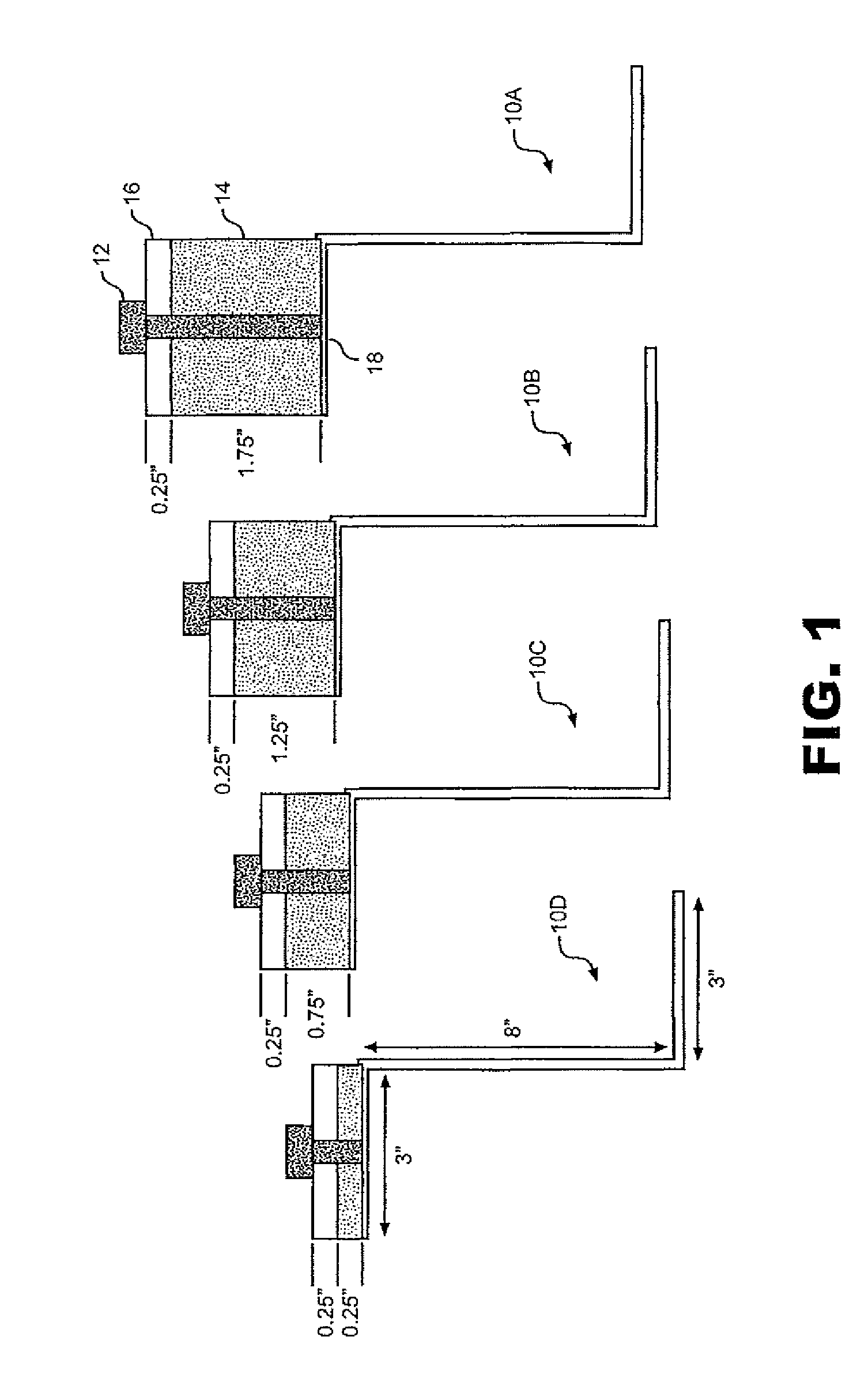
[0011]With initial reference to FIG. 1, base frames 10a-10d represent plural base frame configurations of a building. This figure is basically presented to illustrate that base frames 10a-10d represent a fair range in material and thermal properties. In general, after the particular building structure of the invention has been meshed, the meshed finite elements are used to conduct a FEA of the structure, employing one of several commercially available FEA processors which utilize the mesh area elements of the modeled object to analyze the effect of boundary value field equations. At this point, it should be realized that finite element analysis is used herein to cover various known finite analysis techniques, including finite element and finite difference techniques. Once the analysis is conducted, the results may then be studied to identify implications of the particular construction. Although this figure separately illustrates different potential building construction models, the ...


PUM


Abstract

A universal mesh for a building insulation model is established from a template representing a wide range of insulation profiles, with the mesh being used for conducting one, two or three-dimensional finite element analysis (FEA) regarding thermal insulation factors for the building. The system and method take into account a wide range of heat related factors, including structural materials of the building, insulation components encompassing both insulation materials employed in the building process and established air pockets or gaps, and even fasteners used in the construction process.

Description

TECHNICAL FIELD AND INDUSTRIAL APPLICABILITY OF THE INVENTION[0001]The present invention pertains to the art of finite element analysis and, more particularly, to modeling and analyzing insulation parameters for buildings using finite element analysis.BACKGROUND OF THE INVENTION[0002]Finite element analysis (FEA) is a computer simulation technique used in engineering analysis, most particularly, a methodology for numerical solutions of engineering problems involving differential equations. In general, FEA consists of modeling an object as a collection of elements and analyzing the model to determine information regarding the effects of heat transfer, mechanical stress, thermal stress and the like on the object. In a pre-processing stage, a geometric model is developed of a structure to be analyzed. The model essentially takes into account main structural parameters considered to be important for the actual component. Once the geometric model has been created, a meshing procedure is ...

Claims


Application Information

Patent Timeline
Patent Type & Authority Patents(United States)
IPC IPC(8): G06F17/50
CPCG06F17/5004G06F17/5018G06F2217/16Y02T10/82G06F30/13G06F30/23G06F2111/10
Inventor CHOUDHARY, MANOJ K.KASPRZAK, CHRISTOPHER P.
Owner OWENS CORNING INTELLECTUAL CAPITAL LLC
Learn More