
Adjustable constant current source with continuous conduction mode (“CCM”) and discontinuous conduction mode (“DCM”) operation

a constant current source and continuous conduction mode technology, applied in the field of signal processing, can solve problems such as the error of differential non-linearity (dnl) in the effective current digital-to-analog converter

Inactive Publication Date: 2012-05-15
SIGNIFY HLDG BV
View PDF239 Cites 28 Cited by
  • Summary
  • Abstract
  • Description
  • Claims
  • Application Information

AI Technical Summary

Benefits of technology

The patent describes a converter system that can operate in two modes: Discontinuous Conduction Mode (DCM) and Continuous Conduction Mode (CCM). The converter system includes a converter power stage with an inductor and a control switch. The converter power stage provides an average current, and a current controller is used to measure the inductor value and the input-to-output conversion ratio. The technical effect of this patent is to provide a flexible and efficient converter system that can operate in different modes and accurately measure the input-to-output conversion ratio.

Problems solved by technology

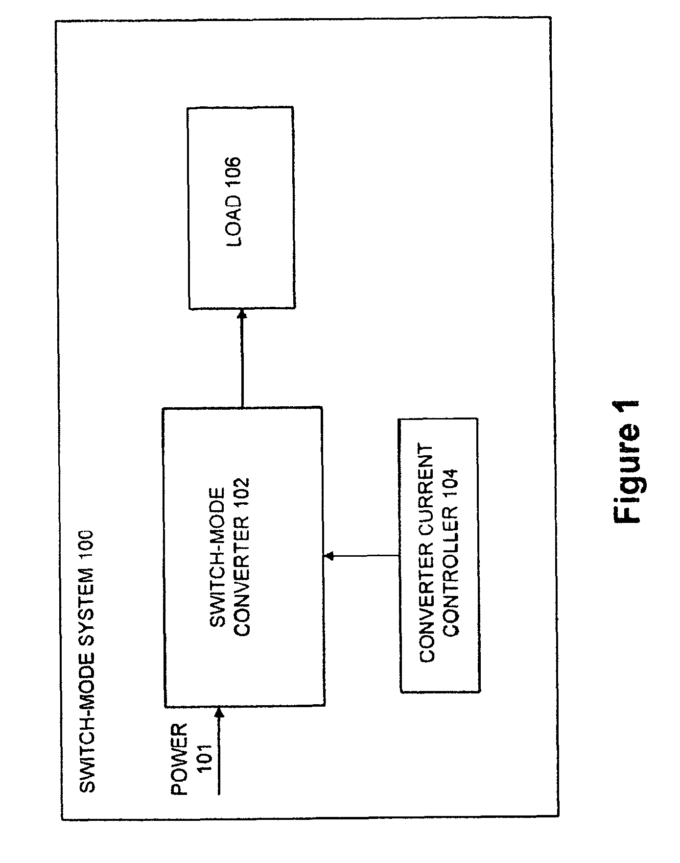
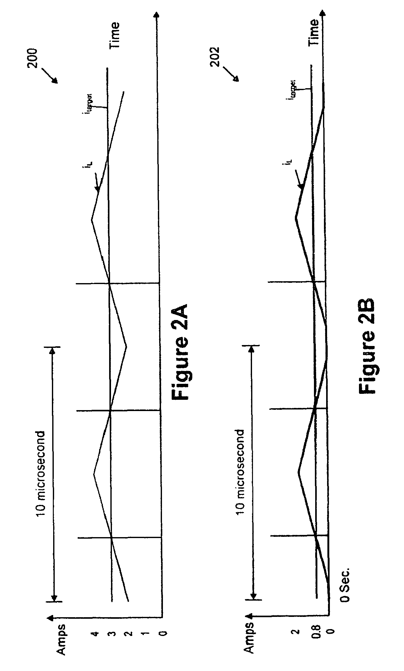
However, providing a smooth transition between CCM and DCM for a converter power stage 102 has its challenges.
Any inaccuracy will cause a differential non-linearity (“DNL”) error in the effective current Digital-to-Analog Converter (“DAC”).

Method used


Image

  • Adjustable constant current source with continuous conduction mode (“CCM”) and discontinuous conduction mode (“DCM”) operation
  • Adjustable constant current source with continuous conduction mode (“CCM”) and discontinuous conduction mode (“DCM”) operation
  • Adjustable constant current source with continuous conduction mode (“CCM”) and discontinuous conduction mode (“DCM”) operation

Examples


Embodiment Construction

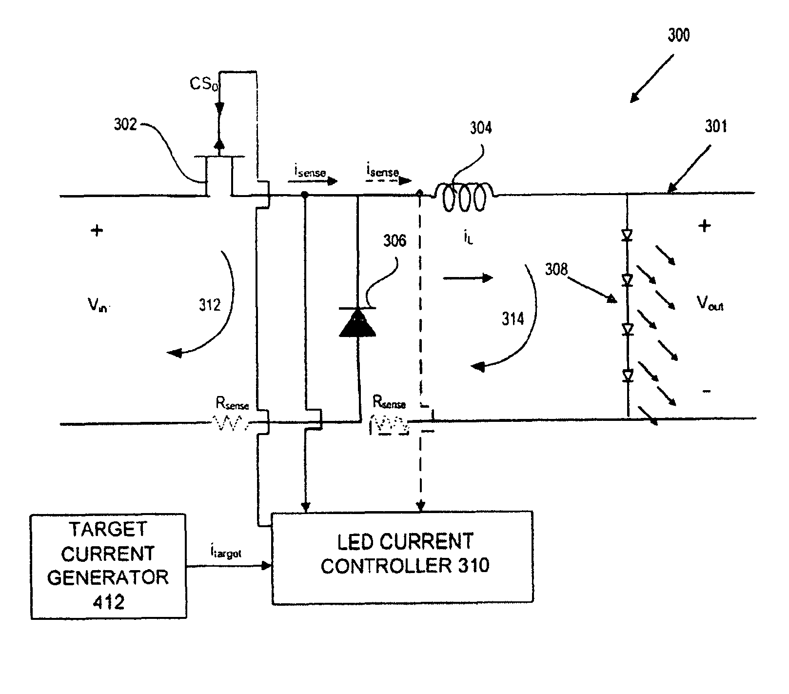
[0019]FIG. 3 depicts details of an Light Emitting Diode (“LED”) lighting system 300 having an exemplary switch-mode buck converter power stage 301 controlled by a Light Emitting Diode. (“LED”) current controller 310 for driving LEDs 308. LED lighting system 300 is an exemplary system illustrating an embodiment of the present invention, and the present invention is not in any way limited to an LED lighting system nor the use of a buck converter, LED current controller, and LEDs. The present invention can also be used for other suitable applications as well as utilize other converters / converter power stages (e.g., boost converters) or controllers.

[0020]Switch-mode buck converter power stage 301 comprises a control switch (e.g., Field Effect Transistor (“FET”)) 302 having a source and drain coupled in series with an inductor 304 as shown in FIG. 3. The source of FET 302 is coupled to a positive side of input voltage Vin. Diode 306 is coupled across the input voltage Vin in which a firs...


PUM


Abstract

A converter system and method of operating a converter system are disclosed. The converter system comprises a converter power stage that can operate in a Discontinuous Conduction Mode (DCM) in a range of output currents and a Continuous Conduction Mode (CCM) in another range of output currents. The converter power stage includes at least an inductor with an inductor value and a control switch. The converter power stage provides an average current. A current controller is coupled to the converter power stage. When the converter power stage operates in DCM, the converter power stage provides the average current and the current controller is configured to measure the inductor value of the inductor. Furthermore, the current controller can also be configured to measure an input-to-output conversion ratio from the converter power stage.

Description

CROSS-REFERENCE TO RELATED APPLICATION[0001]This application is related to and cross-references U.S. application Ser. No. 12 / 107,613 entitled “Power Factor Correction (PFC) Controller and Method Using a Finite State Machine to Adjust the Duty Cycle of a PWM Control Signal” filed on Apr. 22, 2008 (Inventor: John Melanson); U.S. application Ser. No. 12 / 110,714 filed on Apr. 28, 2008 entitled “Discontinuous Conduction Mode (DCM) Using Sensed Current for a Switch-Mode Converter” (Inventor: John Melanson); and U.S. application Ser. No. 12 / 113,536 filed on May 1, 2008 entitled “Switch-Mode Converter Operating in a Hybrid Discontinuous Conduction Mode (DCM) / Continuous Conduction Mode (CCM). That Uses Double or More Pulses in a Switching Period” (Inventor: John Melanson).BACKGROUND OF THE INVENTION[0002]1. Field of the Invention[0003]The present invention relates in general to the field of signal processing, and, more specifically, to apparatuses and methods for providing an adjustable cons...

Claims


Application Information

Patent Timeline
Patent Type & Authority Patents(United States)
IPC IPC(8): G05F1/40H05B44/00
CPCH02M3/156H02M3/158H05B33/0815Y02B20/347Y02B20/30H05B45/38H05B45/375H05B45/37
Inventor MELANSON, JOHN LAURENCE
Owner SIGNIFY HLDG BV
Learn More