
Liquid container and remanufacturing method of liquid container

a liquid container and remanufacturing technology, applied in metal-working devices, printing, writing implements, etc., can solve the problems of shortening the liquid filling time and reducing the liquid filling pressur

Active Publication Date: 2012-05-15
SEIKO EPSON CORP
View PDF22 Cites 18 Cited by
  • Summary
  • Abstract
  • Description
  • Claims
  • Application Information

AI Technical Summary

Benefits of technology

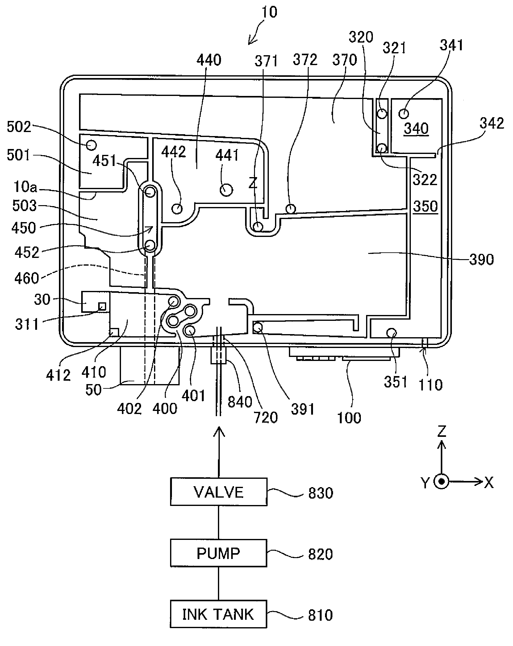
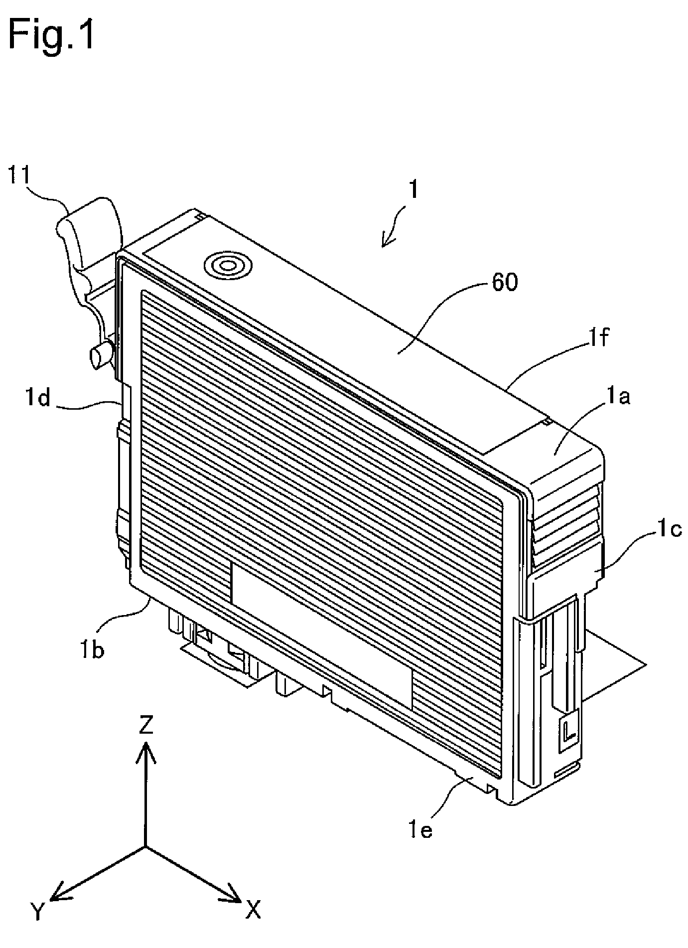
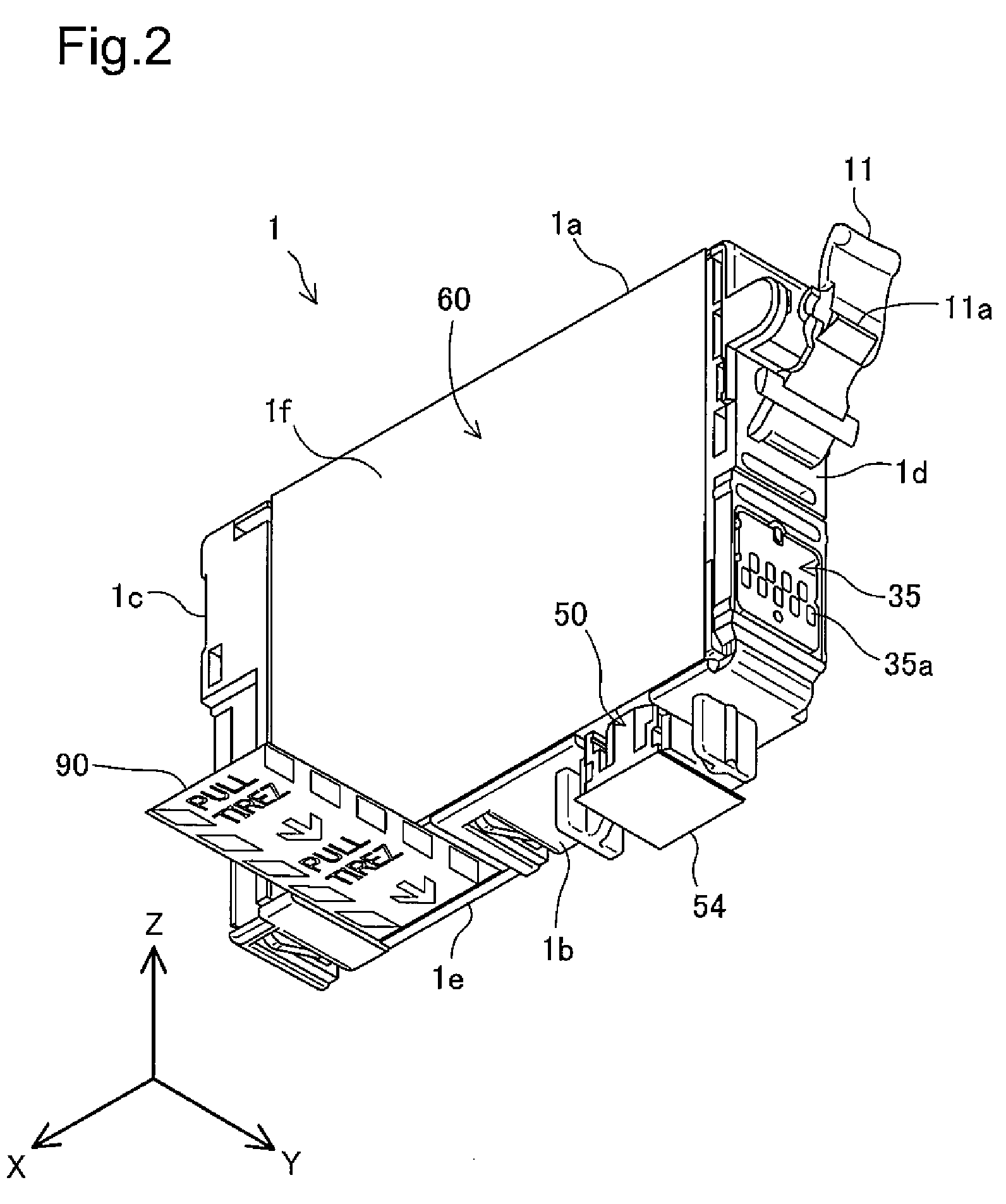
The present invention provides a method for efficiently refilling a liquid container without damaging its functions. The liquid container is designed with a first chamber for storing the liquid, a second chamber in communication with the first chamber for storing the liquid, a sensor for detecting the consumption level or remaining level of the liquid, a liquid feeder for supplying the liquid to the liquid consuming device, an air open structure for connecting the first chamber with the outside air, a bubble trap flow path for trapping bubbles, a bubble trap chamber for trapping bubbles, and an inlet for injecting the liquid into the second chamber. The method reduces the volume of liquid flowing through the bubble trap flow path, decreasing the required liquid filling pressure or shortening the liquid filling time. The liquid container also includes a sealing member for sealing the inlet. The technical effects of this invention include efficient refilling of the liquid container, reduced risk of damage to its functions, and improved user experience.

Problems solved by technology

This arrangement thus desirably decreases the required liquid filling pressure or shortens the liquid filling time to attain the efficient liquid refill.

Method used


Image

  • Liquid container and remanufacturing method of liquid container
  • Liquid container and remanufacturing method of liquid container
  • Liquid container and remanufacturing method of liquid container

Examples


modification 1

C-1. Modification 1

[0095]The ink cartridge remanufacturing process of the embodiment opens and closes the air hole 100 at the ink filling step. One modification may keep the air hole 100 in the closed position and form another hole in the flat surface of the air chambers 320 to 360 to open and close the hole at the ink filling step. The hole formed in the flat surface is more readily opened and closed than the air hole 100 formed in the non-flat surface.

modification 2

C-2. Modification 2

[0096]The ink cartridge remanufacturing process of the embodiment fills the ink in the state of sucking in the liquid feeder 50 at step S650. One modified processing flow of the ink cartridge remanufacturing process may fill the ink in the state of sucking in the air hole 100 at step S630 in addition to or in place of the suction of the liquid feeder 50. This modification enables the injected ink to be smoothly and quickly introduced into the tank chamber 370, while enhancing the discharge of the air.

[0097]Another modified processing flow of the ink cartridge remanufacturing process may fill the ink after the pressure reduction of the inside of the cartridge body 10, for example, by sucking the air out of the cartridge body 10 through a needle inserted into the liquid feeder 50 or the air hole 100 or by placing the cartridge body 10 under reduced pressure and reducing the internal pressure of the cartridge body 10 via the liquid feeder 50 or the air hole 100. This...

modification 3

C-3. Modification 3

[0098]The ink cartridge remanufacturing process of the embodiment first fills the ink into the end chamber 390 and the tank chamber 370 (step S630) and subsequently fills the ink into the space from the bubble trap flow path 400 to the liquid feeder 50 (step S650). This sequence is, however, not essential but may be reversed. Either one of the ink filling step may be omitted according to the requirements.


PUM

PropertyMeasurementUnit
diameteraaaaaaaaaa
internal pressureaaaaaaaaaa
diameteraaaaaaaaaa

Abstract

According to one aspect of the invention, a remanufacturing method of a liquid container forms an inlet in a downstream wall surface of a second chamber, which defines part of a bottom face of the liquid container. In the state of closing a liquid feeder and opening an air open structure, the remanufacturing method injects a liquid through the inlet to fill the second chamber with the liquid. In the state of opening the liquid feeder and closing the air open structure, the remanufacturing method injects the liquid through the inlet to fill a space from the second chamber to the liquid feeder with the liquid. The remanufacturing process seals the inlet after completion of the injection of the liquid. This arrangement enables the liquid to be efficiently refilled into the liquid container without damaging the functions of the liquid container.

Description

CROSS-REFERENCE TO RELATED APPLICATION[0001]The present application claims priority from Japanese application P2008-169048A filed on Jun. 27, 2008, the contents of which are hereby incorporated by reference into this application.BACKGROUND[0002]1. Field of the Invention[0003]The present invention relates to a liquid refill technique of refilling a liquid into a liquid container structured to store the liquid, which is to be supplied to a liquid consuming device.[0004]2. Description of the Related Art[0005]In ink-jet printers, in response to detection of out-of-ink with consumption of ink stored in an ink cartridge, the used ink cartridge is generally replaced with a new ink cartridge. As ink cartridges are recycled, more active approaches for the more efficient use of resources have been demanded and discussed. One approach refills ink into the used ink cartridge. Some techniques have been proposed for ink refill in the ink cartridge as disclosed in, for example, Japanese Patent Lai...

Claims


Application Information

Patent Timeline
Patent Type & Authority Patents(United States)
IPC IPC(8): B41J2/175
CPCB41J2/17506Y10T29/49401
Inventor WANIBE, AKIHISAISHIZAWA, TAKUSHINADA, SATOSHIMIYAJIMA, CHIAKI
Owner SEIKO EPSON CORP
Learn More