Electromechanical relay and method of making same

a technology of electromechanical relays and relays, applied in the field of relays, can solve the problems of large coil size, high unit-to-unit variability and high unit cost, and the general structure of assembly-line processes is generally relatively complicated, and is difficult to fabricate other than using conventional winding methods

Inactive Publication Date: 2012-05-08
MAGVENTION (SUZHOU) LTD
View PDF13 Cites 1 Cited by
  • Summary
  • Abstract
  • Description
  • Claims
  • Application Information

AI Technical Summary

Problems solved by technology

The individual relays produced by such an “assembly-line” type process generally have relatively complicated structures and exhibit high unit-to-unit variability and high unit cost.
One drawback of these traditional latching relay designs is that they require the coil to generate a relatively large reversing magnetic field in order to transfer the armature from one position to the other.
This requirement mandates a large number of wire windings for the coil, making the coil size large and impossible or very difficult to fabricate other than using conventional winding methods.
Each of the prior arts, though providing a unique approach to make latching electromechanical relays and possessing some advantages, has some drawbacks and limitations.
These drawbacks and limitations can make manufacturing difficult and costly, and hinder their value in practical applications.

Method used


Image

  • Electromechanical relay and method of making same
  • Electromechanical relay and method of making same
  • Electromechanical relay and method of making same

Examples


example 1

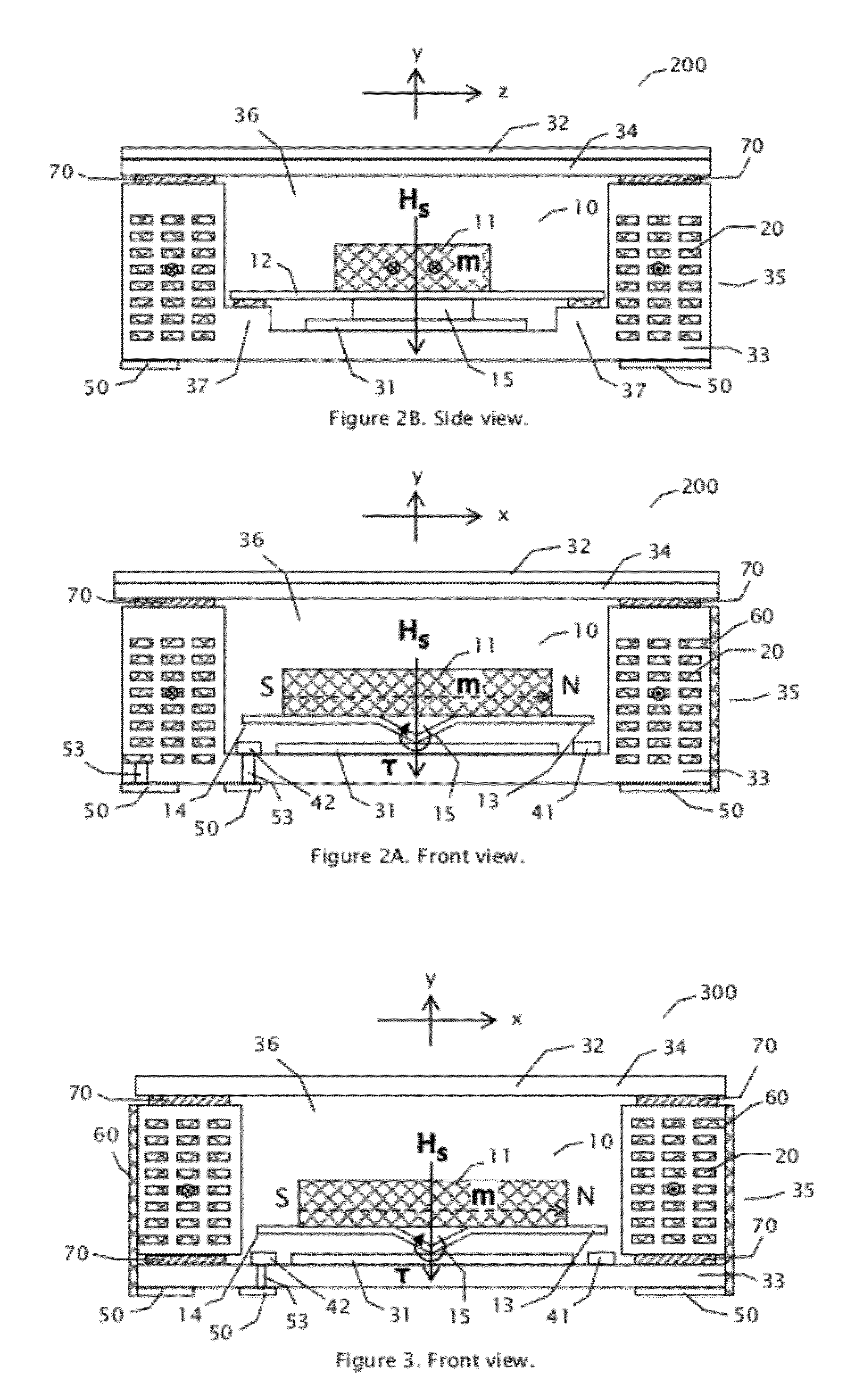
[0053]With reference to FIGS. 2A and 2B, substrate 33, coil 20, spacer 35, stage 37, and electrical contacts 41 and 42, pad 50, and via 53 are made into a unitary ceramic body with typical multi-layer co-fired ceramic processes. Coils 20 and other metal contacts and traces can be applied onto ceramic sheets with screen printing. Coil 20 can be formed by printing planar circulating conductor traces on ceramic sheets and connecting head to tail of adjacent sheets of the conductor traces such that the switching coil current flows in a common circular direction. Cavity 36 and stage 37 can be formed by cutting out suitable regions in the corresponding ceramic sheets. Ceramic sheets are then aligned, stacked and pressed together, and then co-fired to form a rigid structure. A soft magnetic layer 31 is placed on the bottom of cavity 36. First magnet 11 is affixed (by welding or using adhesives) to spring 12 to form movable body 10 with suitable contacts formed at the ends. Movable body 10 ...

example 2

[0054]With reference to FIG. 5, stage 37, electrical contacts 41 and 42, pad 50, and via 53 are formed on a ceramic substrate 33 with typical multi-layer co-fired ceramic processes. Coils 20 are formed by winding conducting wires around an insulating spacer layer 35, and then glued to substrate 33. A soft magnetic layer 31 is affixed to the bottom of cavity 36. First magnet 11 is affixed (by welding or using adhesives) to spring 12 to form movable body 10 with suitable contacts formed at the ends. Movable body 10 is placed into cavity 36 with spring 12 bonded to stage 37. Then cavity 36 is sealed by cover 34 with adhesive layer 70. In this case, cover 34 is made of soft magnetic material. First magnet 11 is then magnetized to the specified orientation and strength.

example 3

[0055]With reference to FIGS. 7A and 7B, stage 37, electrical contacts 41 and 42, pad 50, and via 53 are formed on a ceramic substrate 33 with typical multi-layer co-fired ceramic processes. Soft magnetic layer 31 is glued to substrate 33. Spring 12 (with first magnet 11 pre-affixed to it) is glued to stage 37. Coils 20 are formed by screen printing metal traces on ceramic tapes and multiple layers of screen printed ceramic tapes are aligned, stacked and pressed together, and then co-fired. Coil 20 is glued to spring 12. Cover 34 is glued to coil 20. Soft magnetic layer 32 is glued to cover 34. Adhesive layer 70 is used between various layers to facilitate bonding.

[0056]It is understood that a variety of methods can be used to fabricate the electromechanical relay. These methods include, but not limited to, semiconductor integrated circuit fabrication methods, printed circuit board fabrication methods, micro-machining methods, co-fired ceramic processes, and so on. The methods inclu...


PUM

PropertyMeasurementUnit
coercivityaaaaaaaaaa
permanent magnetization momentaaaaaaaaaa

Abstract

A relay comprises a movable body placed in a cavity which is formed on a substrate and surrounded by a spacer layer and sealed by a cover layer. The movable body comprises a first magnet which is permanently magnetized and has at least a first end. A nearby switching electromagnet, when energized, produces a switching magnetic field which is primarily perpendicular to the magnetization direction of the first magnet and exerts a magnetic torque on the first magnet to force the first magnet and said movable body to rotate and close an electrical conduction path at the first end. Changing the direction of the electrical current in the switching electromagnet changes the direction of the switching magnetic field and thus the direction of the magnetic torque on the first magnet, and causes the first magnet and said movable body to rotate in an opposite direction and opens the electrical conduction path at the first end. The first magnet can comprise multiple magnetic layers to form relatively closed magnetic circuits with other magnetic components. Latching and non-latching types of relays can be formed by appropriately using soft and permanent magnets as various components.

Description

CROSS-REFERENCE TO RELATED APPLICATIONS[0001]This patent application claims the benefit of U.S. Provisional Patent Application Ser. No. 61 / 165,460, filed on Mar. 31, 2009, which is hereby incorporated by reference. This application is a continuation-in-part of U.S. application Ser. No. 11 / 534,655, filed on Sep. 24, 2006, now U.S. Pat. No. 7,482,899 B2 issued on Jan. 27, 2009, which is incorporated herein by reference in its entirety.FIELD OF THE INVENTION[0002]The present invention relates to relays. More specifically, the present invention relates to electromechanical relays and to methods of making electromechanical relays.BACKGROUND OF THE INVENTION[0003]Relays are electromechanical switches operated by a flow of electricity in one circuit and controlling the flow of electricity in another circuit. A typical relay consists basically of an electromagnet with a soft iron bar, called an armature, held close to it. A movable contact is connected to the armature in such a way that the...

Claims


Application Information

Patent Timeline
Patent Type & Authority Patents(United States)
IPC IPC(8): H01H51/22H01H9/00
CPCH01H1/0036H01H2001/0042Y10T29/49078H01H2050/007H01H2036/0093
Inventor SHEN, JUN
Owner MAGVENTION (SUZHOU) LTD
Why Eureka
Try Eureka