
Faster image processing

a fast, image processing technology, applied in the field of image processing, can solve the problems of less than acceptable, noise and artificial spikes in the signal, and the inability to transmit video signals with the full resolution and quality of television, and achieve the effect of increasing the compression ratio and more loss

Inactive Publication Date: 2012-05-01
MUSICQUBED INNOVATIONS LLC
View PDF77 Cites 14 Cited by
  • Summary
  • Abstract
  • Description
  • Claims
  • Application Information

AI Technical Summary

Benefits of technology

"The present invention provides methods for improving image processing and compression by copying image data between memory spaces and optimizing processing with CPU intensive processing. The invention also includes methods for compressing and decompressing video signals with reduced latency and bandwidth requirements for transmission. Additionally, the invention provides methods for distinguishing between regions of an image, selecting the most important parts of an image for higher quality display, and filtering noise from images. The invention also reduces the size of the data buffer and bandwidth required for transmitting video streams."

Problems solved by technology

However the transmission of video signals with the full resolution and quality of television is still out of reach.
A number of different approaches have been taken but each has resulted in less than acceptable results.
In the case where the image is generated based on sampled data, such as an ultrasound machine, there is often noise and artificial spikes in the signal.
Florescent or improper lighting may cause a solid background to flicker or appear grainy.
Such noise exists in the real world but may reduce the quality of the perceived image and lower the compression ratio that could be achieved by conventional methods.
These simple approaches by themselves have failed to achieve the necessary compression ratios.
This approach also has failed to achieve the necessary compression ratios.
These approaches require extensive computer processing and have failed to achieve the necessary compression ratios.
While these dictionary-based algorithms are popular, these approaches require extensive computer processing and have failed to achieve the necessary compression ratios.
However this loss results in certain blocks of the image being compressed such that areas of the image have a blocky appearance and the edges of the 8 by 8 blocks become apparent because they no longer match the colors of their adjacent blocks.
Another disadvantage of JPEG is smearing.
The true edges in an image get blurred due to the lossy compression method.
MPEG suffers from the same blocking and smearing problems as JPEG.
These approaches require extensive computer processing and have failed to achieve the necessary compression ratios without unacceptable loss of image quality and artificially induced distortion.
H.263 compresses in real time but does so by sacrificing image quality resulting in severe blocking and smearing.
These approaches require extensive computer processing and generally cannot be completed in real time.
However these color plane separations are not done to reduce data size or to aid compression.

Method used


Image

  • Faster image processing
  • Faster image processing
  • Faster image processing

Examples


Embodiment Construction

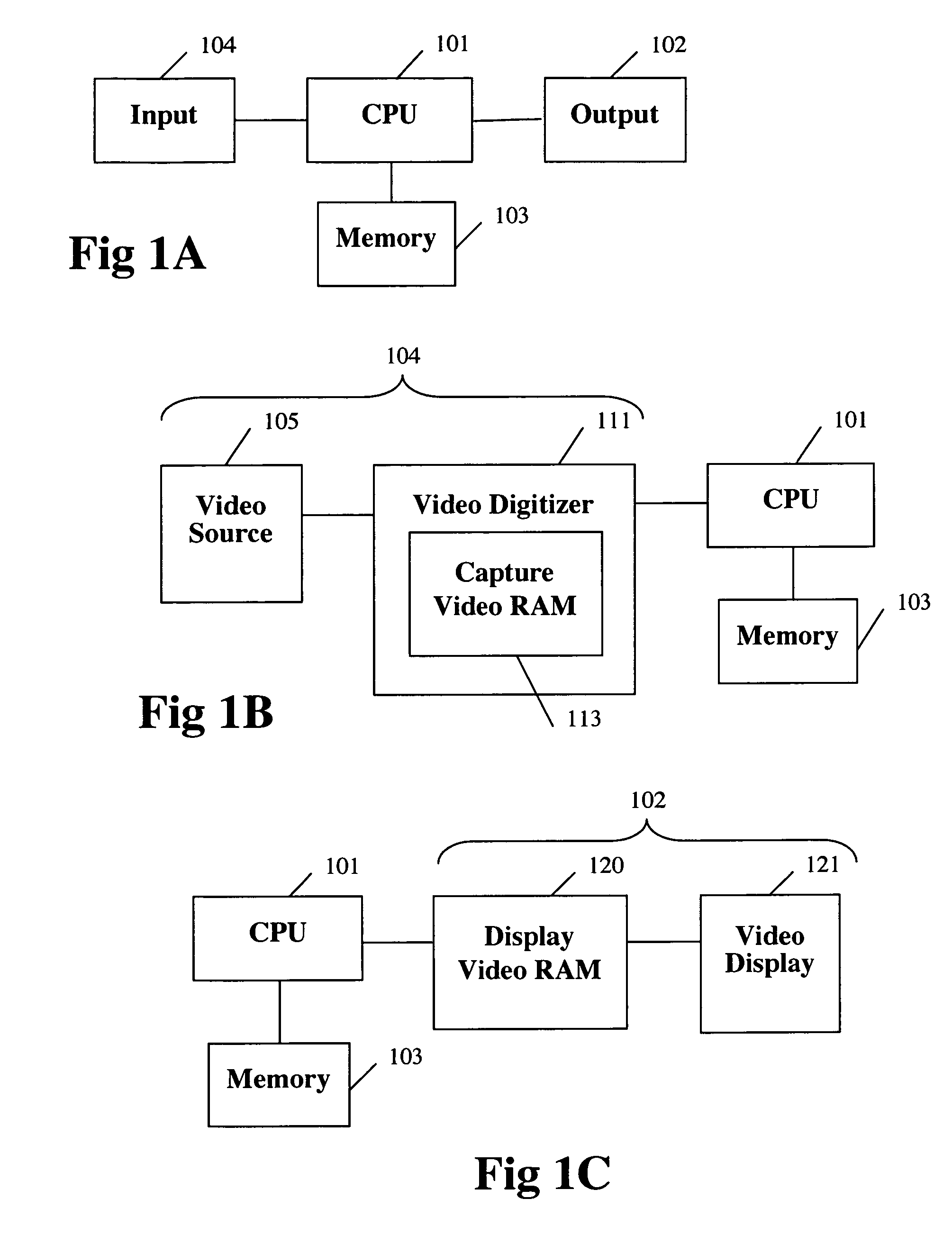
FIG. 1A to 1C—Computer Architectures

[0160]FIG. 1A is a block diagram showing the basic components of a computer, comprising an input 104, a CPU 101, an output 102, and memory 103.

[0161]FIG. 1B shows an embodiment of the computer input 104 specialized to input video data. A video source 105 is connected to a video digitizer 111. The video digitizer 111 converts the analog video signal from the video source 105 to a digital format. Some video digitizers transfer the video data to memory 103 for storage. Alternatively, some video digitizers contain capture video RAM 113 which can store the captured video data on the video digitizer 111 hardware without using memory 103 for storage.

[0162]FIG. 1C shows an embodiment of the computer output 102 specialized to output video data. A video display 121 (also knows as a computer monitor) displays graphical information based on data contained in a display video RAM 120. Programs running on the CPU 101 determine the contents of the display video R...


PUM


Abstract

Methods, medium, and machines associated with image processing performance are disclosed. Image data may be copied from input memory to main memory before performing CPU intensive operations, and efficiently copied from memory thereafter. CPU intensive operations may include decryption, decompression, image enhancement, or reformatting. Real time compression may be achieved by sub-sampling each frame. A separate plane compression aspect may provide for distinguishing between regions of an image, separating and / or masking the original image into multiple image planes, and compressing each separated image plane with a compression method that is optimal for its characteristics.

Description

CROSS-REFERENCE TO RELATED APPLICATIONS[0001]This application is a continuation in part of co-pending application Ser. No. 11 / 820,300 and of application Ser. No. 09 / 758,573.[0002]U.S. patent application Ser. No. 09 / 758,573, filed on Jan. 10, 2001, now U.S. Pat. No. 7,671,864, issued Mar. 2, 2010, and entitled “FASTER IMAGE PROCESSING” is incorporated by reference.[0003]U.S. patent application Ser. No. 11 / 820,300, filed on Jun. 18, 2007, and entitled “SEPARATE PLANE COMPRESSION USING A PLURALITY OF COMPRESSION METHODS INCLUDING ZLN AND ZLD METHODS” is incorporated by reference.[0004]This application (through application Ser. No. 11 / 820,300), application Ser. No. 11 / 820,300, and application Ser. No. 09 / 467,721, claim priority under 35 U.S.C. §119(e) of U.S. provisional application Ser. No. 60 / 113,051, filed on Dec. 21, 1998, and entitled “METHODS OF ZERO LOSS (ZL) COMPRESSION AND ENCODING OF GRAYSCALE IMAGES”, which hereby is incorporated by reference.[0005]U.S. patent application Ser...

Claims


Application Information

Patent Timeline
Patent Type & Authority Patents(United States)
IPC IPC(8): H04B1/66
CPCH04N19/115H04N19/61H04N19/187H04N19/17H04N19/164
Inventor ROMAN, KENDYL A.
Owner MUSICQUBED INNOVATIONS LLC
Learn More