
Glass composition and process for sealing void spaces in electrochemical devices

a glass composition and electrochemical device technology, applied in the field of foaming glass compositions, can solve the problems of reducing the efficiency of the device, reducing the output voltage and utility of the device as a power generator, shrinking of glass-containing seals used to couple components within the stack of sofc, etc., to achieve the effect of minimizing adverse chemical reactions and expanding the volume of glass

Active Publication Date: 2012-05-01
BATTELLE MEMORIAL INST
View PDF10 Cites 0 Cited by
  • Summary
  • Abstract
  • Description
  • Claims
  • Application Information

AI Technical Summary

Benefits of technology

The present invention is a glass-sealing composition and process for filling and sealing void spaces in electrochemical devices. The composition includes a preselected glass material containing a gas-releasing (foaming) agent that releases gas at a specific temperature. When heated, the glass expands to fill the void space. The process involves dispensing the glass material into the void space and heating it to induce crystallization, resulting in a seal that prevents leakage. The glass material can be selected from a variety of options, such as sealing glasses, passivation glasses, crystallizing glasses, vitreous glasses, and more. The foaming agent can be strontium carbonate or other carbon dioxide-releasing agents. The composition can be used in solid oxide fuel cells, where the void space can be a tolerance channel or by-pass channel. The technical effect of this invention is to provide a reliable and effective method for sealing void spaces in electrochemical devices.

Problems solved by technology

During thermal curing, however, glass-containing seals used to couple components within an SOFC stack can shrink.
Shrinkage in glass seals used to couple various components can introduce unintentional void spaces, flow paths, gaps, and / or channels within the device that permit undesired consequences to occur including, e.g., unintentional, or redirected, flow of fuel into these void spaces and channels during operation, which reduces the efficiency of the device and can induce associated reductions in output voltages and utility of the device as a power generator.

Method used


Image

  • Glass composition and process for sealing void spaces in electrochemical devices
  • Glass composition and process for sealing void spaces in electrochemical devices
  • Glass composition and process for sealing void spaces in electrochemical devices

Examples


example 1

Glass Paste Form

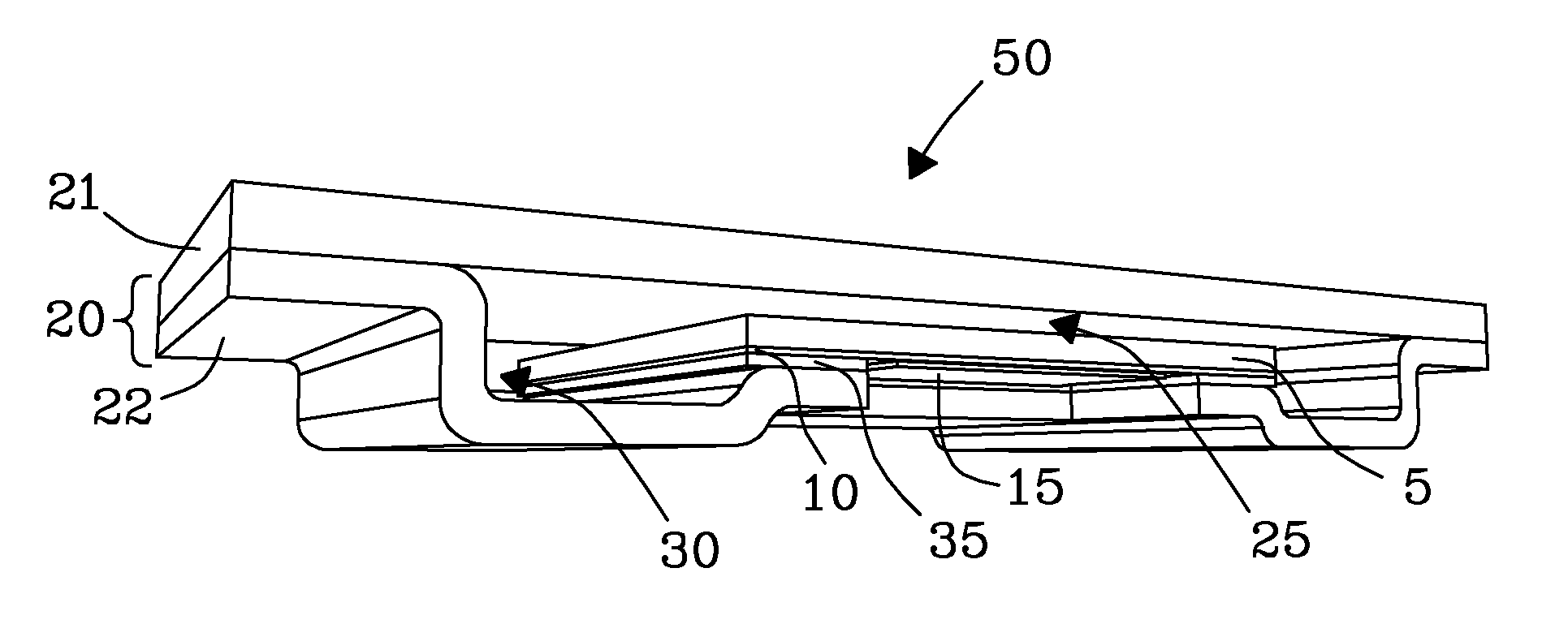
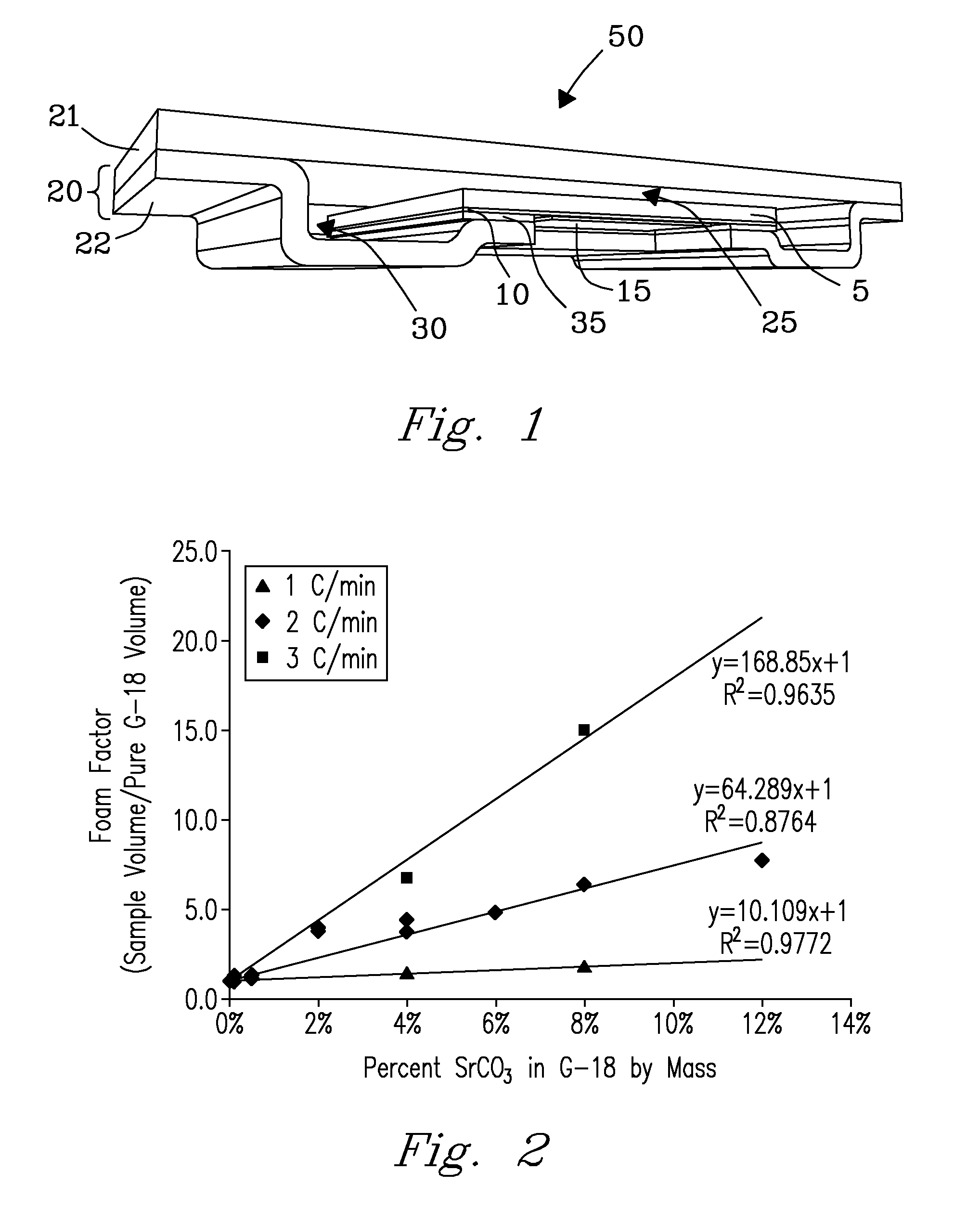
[0045]In an exemplary test, a foaming glass paste containing G-18 glass was dispensed at a uniform rate (e.g., 0.075 g / linear cm) into tolerance channels 30 located between a steel frame 20 of a solid oxide fuel cell 50 on the anode side of the device 50 using a pressurized dispensing tool. A consistent bead of glass paste with an approximately hemispherical cross-section was applied, having typical dimensions: 2-mm wide and 1-mm high. Device components were dried in an oven at 80° C. to remove solvent from the paste. A separator plate 21 was welded to a lower plate 22 to form a cassette, covering the bead of dried paste. A stack (not shown) consisting of five cassettes 50 was assembled. Expansion (i.e., foaming) of the foaming glass paste in the tolerance channels 30 to seal the tolerance channels of the devices 50 was achieved concurrently with stacking of the five cassettes 50 together and coupling them together using a conventional, non-foaming glass. Results dem...


PUM

PropertyMeasurementUnit
temperatureaaaaaaaaaa
melting temperatureaaaaaaaaaa
crystallization temperatureaaaaaaaaaa

Abstract

A glass foaming material and method are disclosed for filling void spaces in electrochemical devices. The glass material includes a reagent that foams at a temperature above the softening point of the glass. Expansion of the glass fills void spaces including by-pass and tolerance channels of electrochemical devices. In addition, cassette to cassette seals can also be formed while channels and other void spaces are filled, reducing the number of processing steps needed.

Description

[0001]This invention was made with Government support under Contract DE-AC05-76RLO1830 awarded by the U.S. Department of Energy. The Government has certain rights in the invention.FIELD OF THE INVENTION[0002]The present invention relates generally to glass compositions, and more particularly to foaming glass compositions and processes for making same.BACKGROUND OF THE INVENTION[0003]Solid oxide fuel cell (SOFC) devices are known and used for the direct production of electricity from standard fuel materials including fossil fuels, hydrogen, and the like by converting chemical energy of a fuel into electrical energy. Fuel cells typically include porous electrode components that are compiled as stacks for conversion of fuels. In a typical SOFC, a solid electrolyte separates the porous metal-based anode from a porous metal or ceramic cathode. Conditioning of solid oxide fuel cells (SOFCs) typically requires a thermal break-in period at a suitable operating temperature in order to integr...

Claims


Application Information

Patent Timeline
Patent Type & Authority Patents(United States)
IPC IPC(8): H01M2/08
CPCC03C8/24C03C11/007H01M8/0282H01M8/0286H01M2008/1293Y02E60/50Y02E60/525
Inventor MEINHARDT, KERRY D.KIRBY, BRENT W.
Owner BATTELLE MEMORIAL INST
Learn More