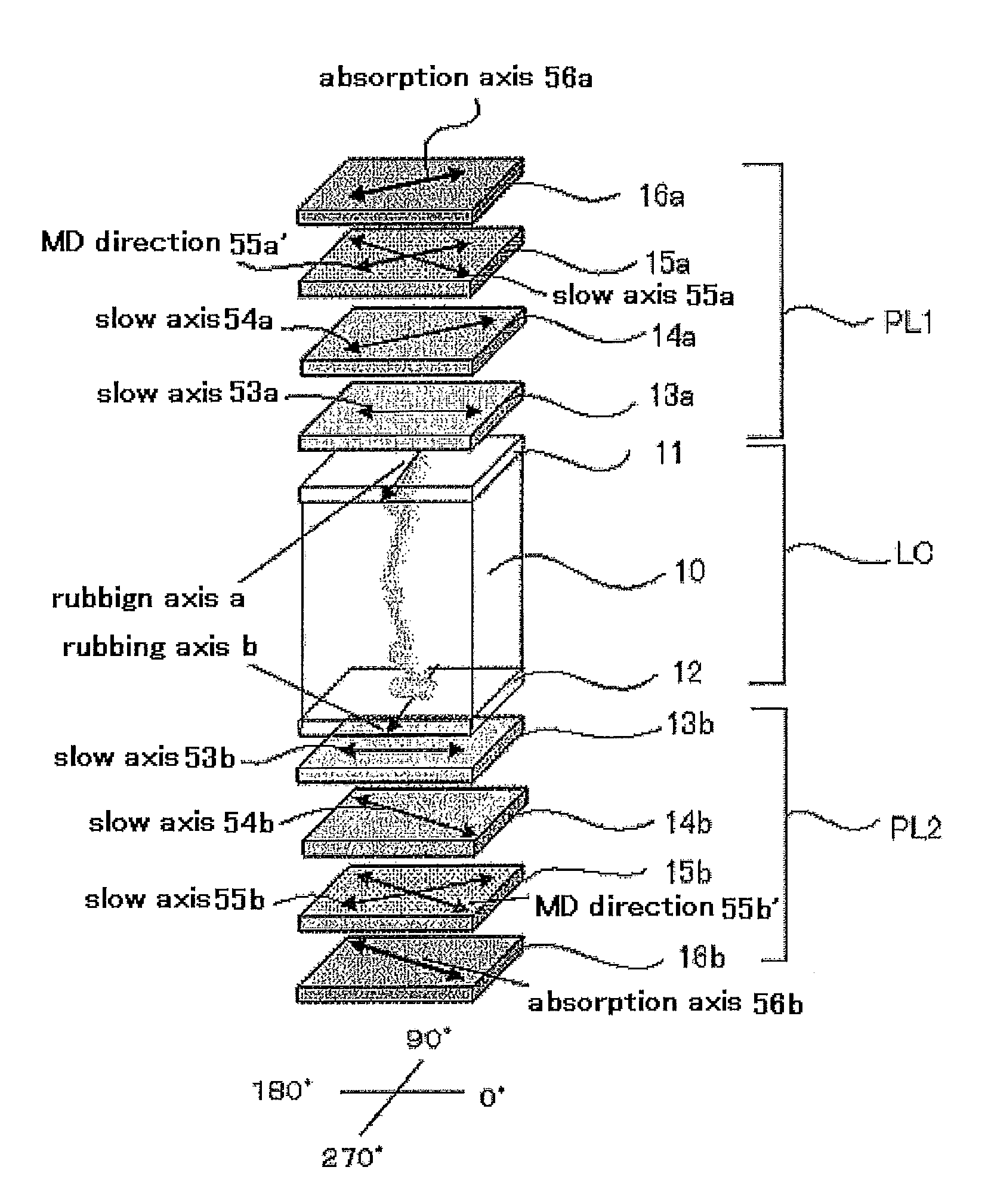
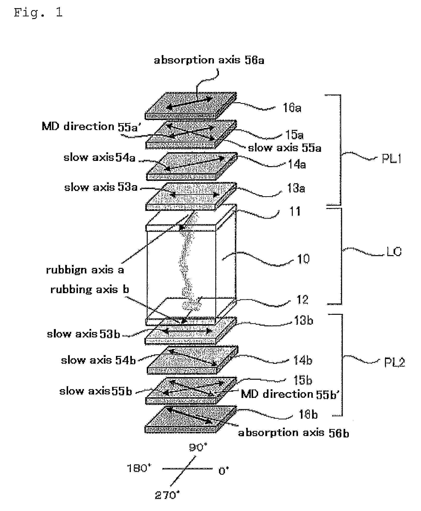
Liquid-crystal display device with at least three optically-anisotropic layers having formulated in-plane retardations
a liquid crystal display and in-plane retardation technology, applied in optics, instruments, optical elements, etc., can solve the problems of additive bleedout, coloration of display images, haze may increase, etc., and achieve the effect of improving viewing angle characteristics
- Summary
- Abstract
- Description
- Claims
- Application Information
AI Technical Summary
Benefits of technology
Problems solved by technology
Method used
Image

Examples
example 1
1. Example 1
1.-1 Formation of Third Optically-Anisotropic Layer
[0298]The following ingredients were put into a mixing tank and stirred under heat to dissolve them, thereby preparing a cellulose acetate solution A.
[0299]
Formulation of Cellulose Acetate Solution ACellulose acetate having a degree of100mas. pts.acetylation of 60.9%Triphenyl phosphate7.8mas. pts.Biphenyldiphenyl phosphate3.9mas. pts.Methylene chloride300mas. pts.Methanol45mas. pts.
[0300]4 parts by mass of cellulose acetate having a degree of acetylation of 60.9% (linter), 25 parts by mass of a retardation enhancer mentioned below, 0.5 parts by mass of fine silica particles (mean particle size: 20 nm), 80 parts by mass of methylene chloride and 20 parts by mass of methanol were put into another mixing tank and stirred under heat to prepare a retardation enhancer solution.
Retardation Enhancer:
[0301]
[0302]34.4 parts by mass of the retardation enhancer solution was mixed with 470 parts by mass of the cellulose acetate solut...
examples 2 to 9
2. Examples 2 to 9
[0345]OCB-mode liquid-crystal display devices were produced and evaluated in the same manner as in Example 1, for which, however, the TAC film used as the second optically-anisotropic layer and / or the TAC film used as the third optically-anisotropic layer were replaced with the TAC films having the properties shown in Table 1.
[0346]Re and Rth of the TAC films were controlled by changing the condition in biaxial stretching treatment.
example 10
3. Example 10
[0347]An OCB-mode liquid-crystal display device was produced and evaluated in the same manner as in Example 1, for which, however, the discotic liquid-crystal of the first optically-anisotropic layer was replaced with a rod-like liquid-crystal NG-1 shown below, and the TAC film used for the second optically-anisotropic layer and the TAC film used for the third optically-anisotropic layer were replaced with the TAC films having the properties shown in Table 1.
[0348]
4. Comparative Examples 1 to 4
PUM
| Property | Measurement | Unit |
|---|---|---|
| thickness | aaaaa | aaaaa |
| angle | aaaaa | aaaaa |
| thickness-direction retardation | aaaaa | aaaaa |
Abstract
Description
Claims
Application Information
 - R&D
- Intellectual Property
- Life Sciences
- Materials
- Tech Scout
- Unparalleled Data Quality
- Higher Quality Content
- 60% Fewer Hallucinations
Browse by: Latest US Patents, China's latest patents, Technical Efficacy Thesaurus, Application Domain, Technology Topic, Popular Technical Reports.
© 2025 PatSnap. All rights reserved.Legal|Privacy policy|Modern Slavery Act Transparency Statement|Sitemap|About US| Contact US: help@patsnap.com