Electromagnetic bandgap structure and printed circuit board
a technology of electromagnetic bandgap and printed circuit board, which is applied in the direction of high frequency circuit adaptation, coupling device connection, waveguide, etc., can solve the problems of printed circuit board, noise problem, and preventing conduction nois
- Summary
- Abstract
- Description
- Claims
- Application Information
AI Technical Summary
Benefits of technology
Problems solved by technology
Method used
Image
Examples
first embodiment
[0140]FIG. 5 is a plan view showing a multi-layered electromagnetic bandgap structure having a stitching via and a printed circuit board having the same in accordance with the present invention. FIG. 10A is a 3-D perspective view showing the electromagnetic bandgap structure of FIG. 5.
[0141]The electromagnetic bandgap structure according to a first embodiment of the present invention can include two metal layers 511 and 512, a plurality of metal plates 531, 532 and 533 placed on a planar surface between the two metal layers 511 and 512, a first stitching via 545 electrically connecting one metal plate 532 to another metal plate 531 and a second stitching via 549 electrically connecting the one metal plate 532 to yet another metal plate 533.
[0142]A dielectric layer 521 and a dielectric layer 522 can be interposed between the metal layer 512 and the plurality of metal plates 531, 532 and 533 and between the plurality of metal plates 531, 532 and 533 and the metal layer 511, respective...
second embodiment
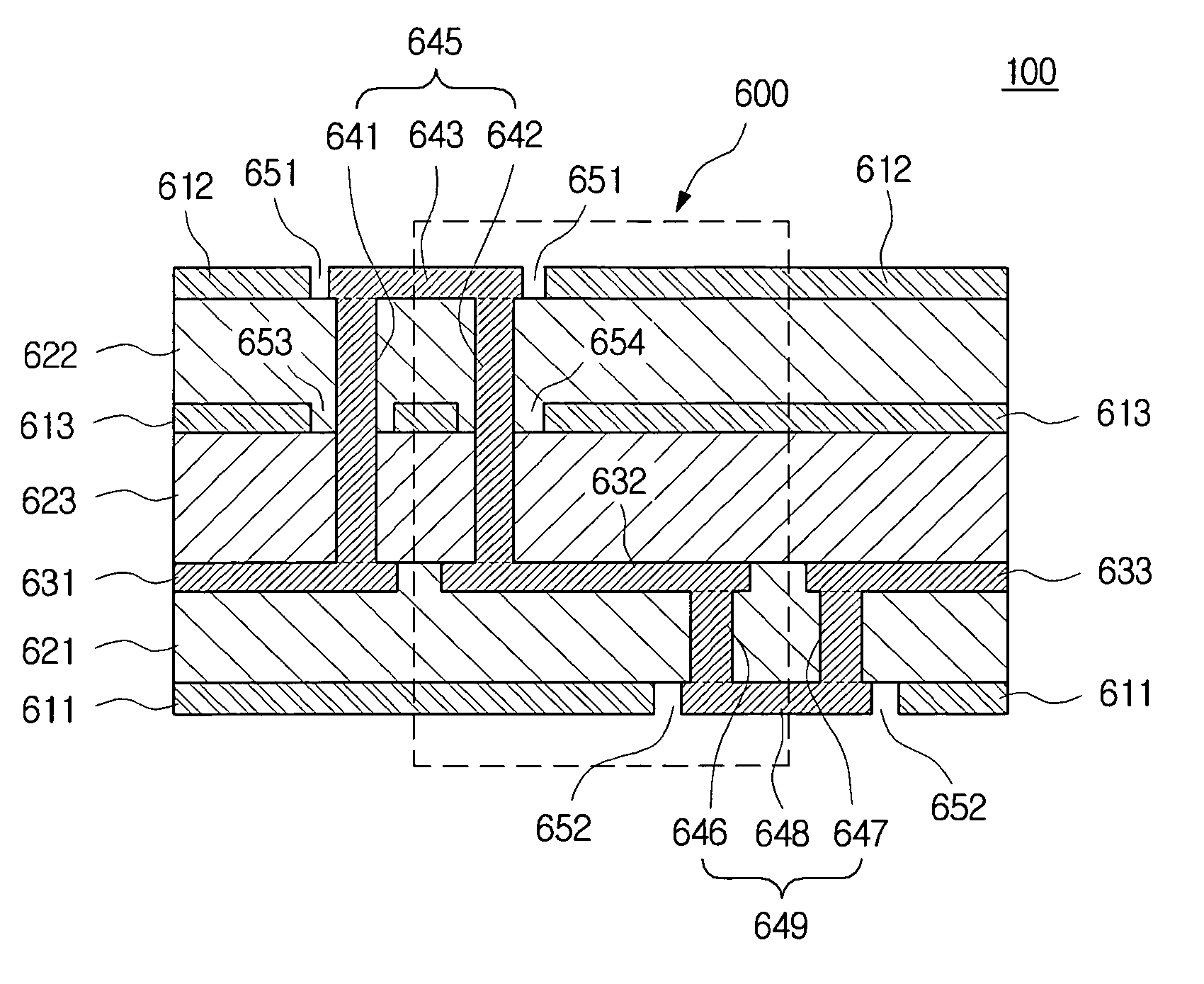
[0155]FIG. 6 is a plan view showing a multi-layered electromagnetic bandgap structure having a stitching via and a printed circuit board having the same in accordance with the present invention. FIG. 11A is a 3-D perspective view showing the electromagnetic bandgap structure of FIG. 6.
[0156]The electromagnetic bandgap structure according to a second embodiment of the present invention can include three metal layers 611 and 612, a plurality of metal plates 631, 632 and 633 placed on a planar surface between any two metal layers 611 and 612, a first stitching via 645 electrically connecting one metal plate 632 to another metal plate 631 and a second stitching via 649 electrically connecting the one metal plate 632 to yet another metal plate 633.
[0157]The electromagnetic bandgap structure in accordance with the second embodiment of the present invention can feature the additional metal layer that is placed between at least one of the two metal layers 611 and 612 and the metal plates 63...
third embodiment
[0174]FIG. 7 is a plan view showing a multi-layered electromagnetic bandgap structure having a stitching via and a printed circuit board having the same in accordance with the present invention.
[0175]The electromagnetic bandgap structure in accordance with a third embodiment of the present invention can include a plurality of metal plates 731, 732 and 733 placed on any one planar surface of a printed circuit board, two metal layers 711 and 712 placed on different planar surfaces below the planar surface on which the metal plates 731, 732 and 733 are stacked, a first stitching via 745 electrically connecting any one 732 of the metal plates 731, 732 and 733 to another metal plate 731 and a second stitching via 749 electrically connecting any one metal plate 732 to yet another metal plate 733.
[0176]A dielectric layer 721 and a dielectric layer 722 can be interposed between the metal plates 731, 732 and 733 and any one metal plate 711 and between the two metal layers 711 and 712.
[0177]F...
PUM
 Abstract
Description
Claims
Application Information
 - R&D
- Intellectual Property
- Life Sciences
- Materials
- Tech Scout
- Unparalleled Data Quality
- Higher Quality Content
- 60% Fewer Hallucinations
Browse by: Latest US Patents, China's latest patents, Technical Efficacy Thesaurus, Application Domain, Technology Topic, Popular Technical Reports.
© 2025 PatSnap. All rights reserved.Legal|Privacy policy|Modern Slavery Act Transparency Statement|Sitemap|About US| Contact US: help@patsnap.com


