
Slotted waveguide antenna stiffened structure

a technology of antenna and stiffened structure, which is applied in the direction of polarised antenna unit combinations, particular array feeding systems, linear waveguide fed arrays, etc., can solve the problems of reducing vehicle performance in the areas of speed, range, endurance and payload, and achieves efficient radio frequency energy radiation, reduce vehicle performance, and reinforce the aircraft skin

Inactive Publication Date: 2012-04-03
THE UNITED STATES OF AMERICA AS REPRESETNED BY THE SEC OF THE AIR FORCE
View PDF7 Cites 40 Cited by
  • Summary
  • Abstract
  • Description
  • Claims
  • Application Information

AI Technical Summary

Benefits of technology

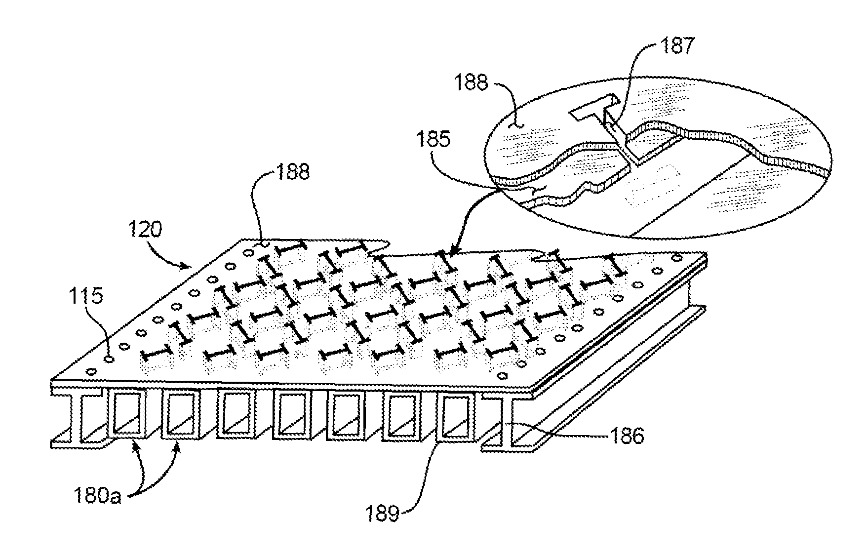
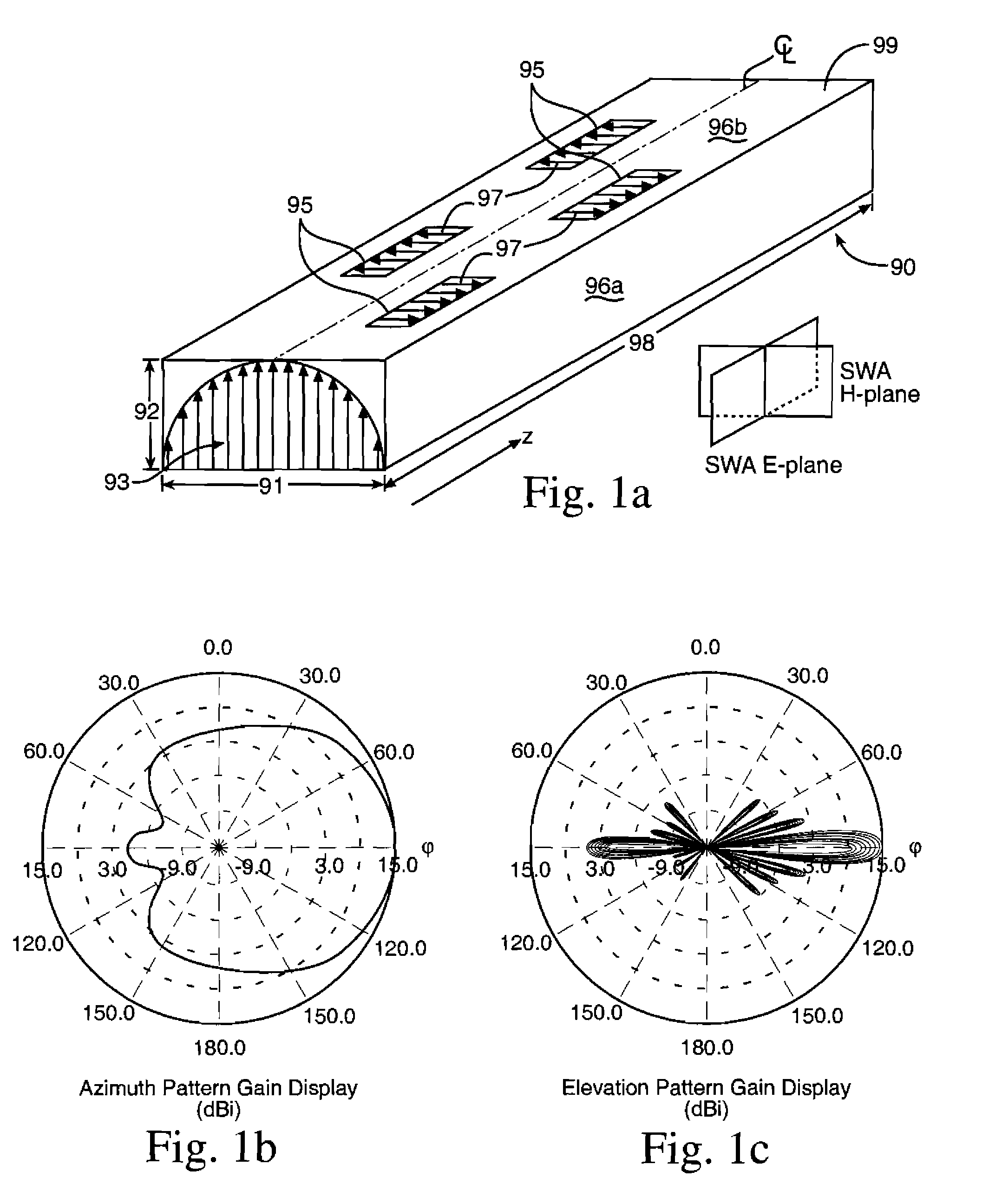
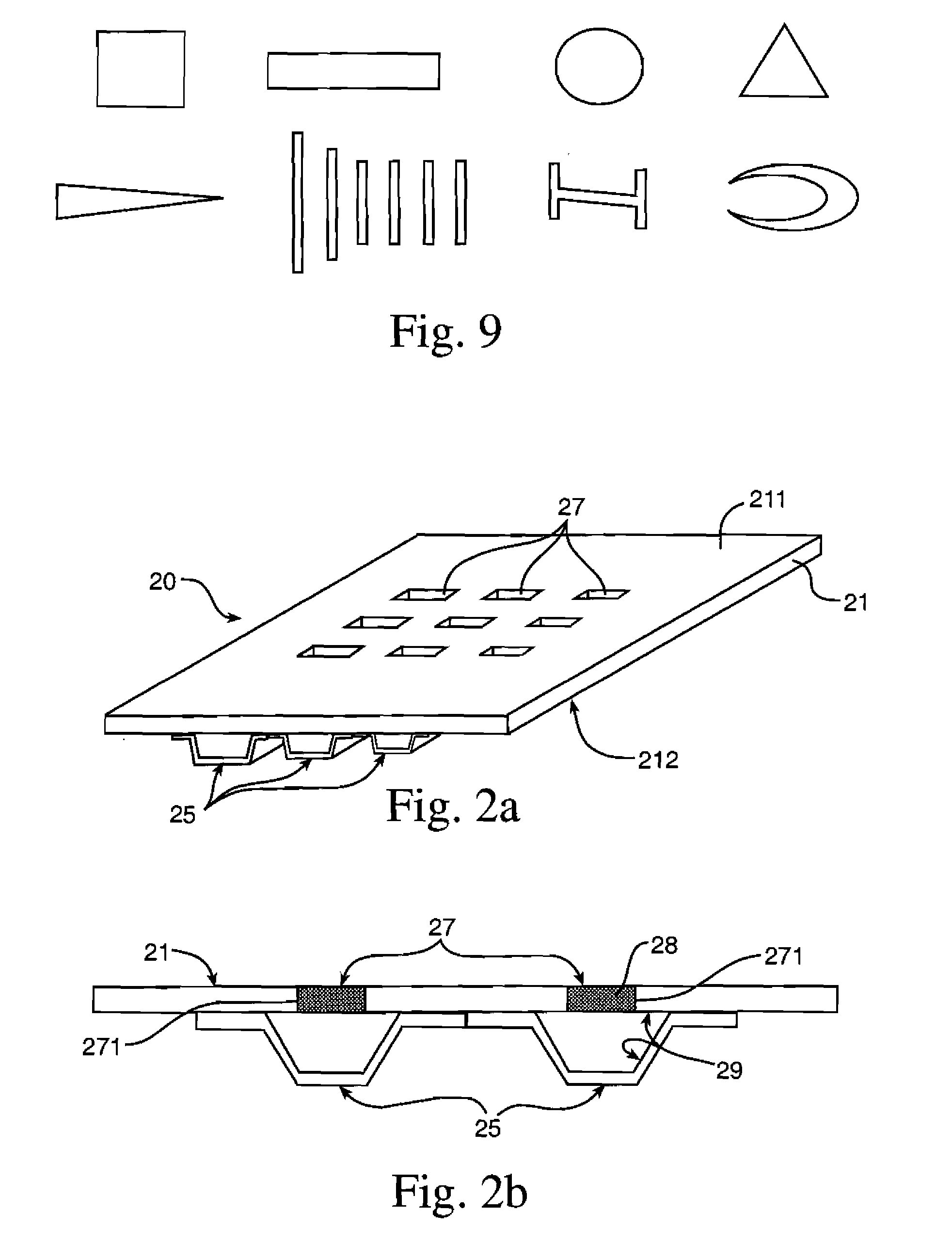
[0007]A slotted waveguide antenna stiffening structure for an aircraft having a conductive aircraft skin. The slotted waveguide antenna stiffening structure including a structural stiffening element reinforcing the aircraft skin. The structural element connected to a radio frequency feed source, the source providing energy with electromagnetic bandwidth to a slotted waveguide antenna having a plurality of slots. The antenna conformal to the aircraft skin and the structural stiffening element, the structural stiffening elements functioning as waveguides for the electromagnetic bandwidth. In one embodiment, a slot sealant encloses the plurality of slots. The slot sealant is preferably a low-loss dielectric that allows efficient radiation of radio frequency energy. Many RF sensor systems can be carried by a single aircraft and the resulting combined antenna weight and size may reduce vehicle performance in the areas of speed, range, endurance and payload. The present invention improves operational effectiveness and performance of the aircraft. This is accomplished by replacing heavy / bulky antennas with lightweight / conformal antennas that have been incorporated into the airframe structure as claimed and disclosed herein.

Problems solved by technology

Many RF sensor systems can be carried by a single aircraft and the resulting combined antenna weight and size may reduce vehicle performance in the areas of speed, range, endurance and payload.

Method used


Image

  • Slotted waveguide antenna stiffened structure
  • Slotted waveguide antenna stiffened structure
  • Slotted waveguide antenna stiffened structure

Examples


Embodiment Construction

[0026]The antennas for some RF systems are relatively heavy / bulky and therefore may degrade the speed, range, endurance and payload of aircraft. It is proposed herein that some performance may be restored by replacing such antennas with lightweight conformal antennas that function as airframe structure. This concept may be particularly advantageous for Small Uninhabited Aerial Vehicles (SUAVs) where weight and aerodynamic drag may significantly degrade performance. The weight of many RF antenna systems, including radars, signals intelligence receivers and jammers are now down to a few kilograms and may be carried as payloads in SUAVs. The advantages of SUAVs are that they can traverse battlefields within useful time periods, be networked, and replaced at relatively low cost. SUAVs fitted with appropriate systems can contribute significantly to the electronic warfare (EW) roles of jamming and suppression of enemy air defenses, electronic support measures and signals intelligence. Oth...


PUM


Abstract

A slotted waveguide antenna stiffened structure for an aircraft having an aircraft skin. The slotted waveguide antenna stiffening structure including a structural stiffening element reinforcing the aircraft skin; the structural element connected to a radio frequency feed source, the source providing energy with electromagnetic bandwidth to a slotted waveguide antenna having a plurality of slots. The antenna conformal to the aircraft skin and the structural stiffening element, the structural stiffening elements functioning as waveguides for the electromagnetic bandwidth. The slots may include a slot sealant enclosing the plurality of slots.

Description

[0001]This application claims the benefit of provisional application 61 / 051,715 filed May 9, 2008 under the provisions of 35 U.S.C. §119(e).RIGHTS OF THE GOVERNMENT[0002]The invention described herein may be manufactured and used by or for the Government of the United States for all governmental purposes without the payment of any royalty.BACKGROUND OF THE INVENTION[0003]The invention relates to an air vehicle concept that simultaneously provides a load bearing and antenna function, herein referred to as a Slotted Waveguide Antenna Stiffened Structure (SWASS) concept. SWASS uses airframe construction, such as hat shaped cross-section stiffened skins, or sandwich stiffened structure skin made from materials such as carbon fiber reinforced composites or aluminum. SWASS uses slot apertures in the skin as RF radiators and the top-hat stiffeners for both structural reinforcement and also as waveguides to feed the slot apertures. In this way, with minimal changes to load bearing skin conf...

Claims


Application Information

Patent Timeline
IPC IPC(8): H01Q1/42
CPCH01Q1/286H01Q1/287H01Q13/22H01Q21/005H01Q21/24
Inventor CALLUS, PAUL J.DE LAHARPE, JOHN D. C.TUSS, JAMES M.BARON, WILLIAM G.KUHL, DAVID G.
Owner THE UNITED STATES OF AMERICA AS REPRESETNED BY THE SEC OF THE AIR FORCE
Learn More