Scupper joint for ship

a ship and joint technology, applied in the field of ship and joint, can solve the problems of increasing the burden on inventory turnover and management, affecting ship construction, and reducing the production cycle, so as to reduce the burden on the ship, reduce the production cycle, and save the cost of manufacturing, development, packaging and transportation.

Inactive Publication Date: 2012-04-03
MARINE TOWN
View PDF12 Cites 8 Cited by
  • Summary
  • Abstract
  • Description
  • Claims
  • Application Information

AI Technical Summary

Benefits of technology

[0009]Hence, the primary objective of the present invention is to provide a scupper joint for a ship, wherein the scupper joint is not made through the known casting process or powder metallurgy process. Instead, the scupper joint has a body based on a piece cut from a seamless stainless steel tube that receives some known processes to have its designed configuration. As compared with the conventional scupper joints, the subject matter of the present invention is advantaged by saving costs in manufacture, development, packing and transportation, reducing a production cycle, thinning the scupper joint, ensuring discarding capacity, less burdening the ship, being highly anticorrosive, and being flexible to meeting customers' various components demands.

Problems solved by technology

Since the casting process requires a long production cycle in addition to expensive modules, for satisfying buyers' unscheduled component demands, the manufacturing may have to produce for inventory, thus adding burden to inventory turnover and management.
Besides, while being hedged about the availability of existing modules, provision of the products is far from flexible.
On the other hand, through the casting process, it is difficult, if not impossible, to make the body 10 have a wall thickness less than 2 mm without causing a high defective rate.
Consequently, the resultant scupper joint is bulky and heavy, thus requiring increased packing and transporting costs.
Moreover, the body 10 made of stainless steel can still rust after long-term contact with water.
As a result, the rust scales can block the hole 101 and significantly weaken the discharging capacity of the scupper joint, rendering a shortened service life of the scupper joint.
However, the expensive materials make the products become too expensive to be classed as economical.
Nevertheless, theses processes require remarkable costs in modules and operation as compared with the aforesaid casting process does.
As a result, the expensive processes make the products become too expensive to be classed as economical.

Method used


Image

  • Scupper joint for ship
  • Scupper joint for ship
  • Scupper joint for ship

Examples


Embodiment Construction

[0020]While a preferred embodiment is provided hereinafter for illustrating the concept of the present invention as described above, it is to be understood that the components of the embodiment shown in the accompanying drawings are depicted for the sake of easy explanation and need not to be made in scale. Moreover, in the following description, resemble components are indicated by the respectively identical numerals.

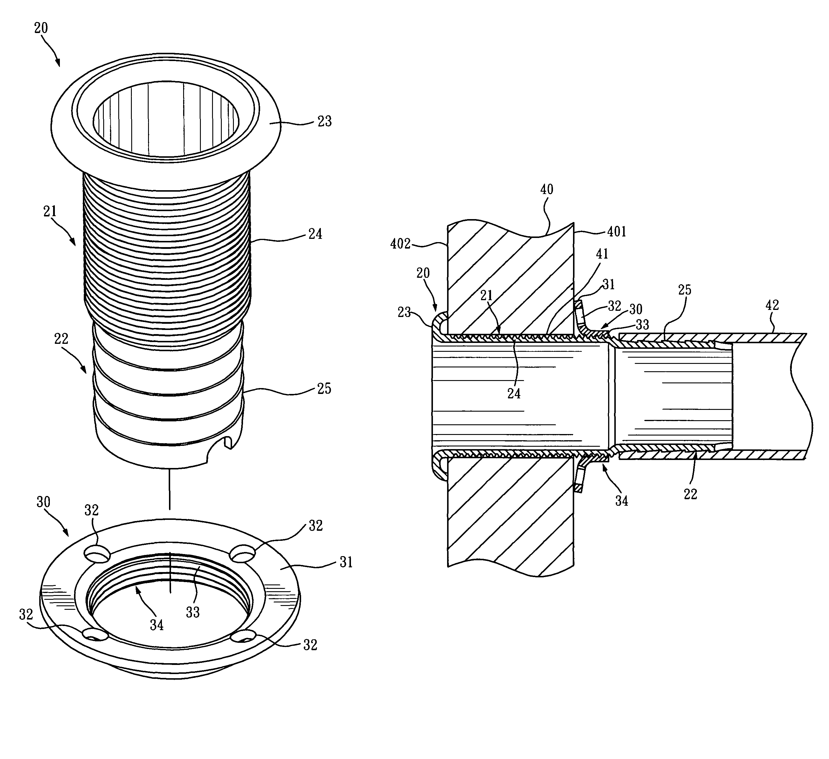
[0021]Please refer to FIGS. 3 through 6. A scupper joint disclosed in the present invention comprises a body 20 and a nut 30 that is mounted around and thereby coupled with the body 20.

[0022]The body 20 has a tubular structure that includes a first section 21 and a second section 22. The first section 21 and the second section 22 are intercommunicated and extending linearly, axially inside the body 20. Therein, the second section 22 is formed through a tube reducing process so that its inner diameter and its outer diameter are smaller than those of the first section 21...


PUM


Abstract

A scupper joint for a ship includes a body and a nut. The body has a tubular structure as a piece cut from a seamless tube. The tubular structure has a first section and a second section. The first section has a flange at one end thereof as an evagination and a threaded segment at an outer periphery thereof. The second section has at least one annular protrusion at an outer periphery thereof. The nut has an annular structure. The tubular structure has an end evaginated to form a flange and has an inner wall threaded to form a threaded segment. The threaded segment of the nut and the threaded segment of the first section are configured to couple with each other.

Description

BACKGROUND OF THE INVENTION[0001]1. Technical Field[0002]The present invention relates to scupper joints for ships. More particularly, the present invention relates to a scupper joint provided at a lower lateral portion of a ship hull, wherein the scupper joint is connected with a pumping plant installed in the ship hull for allowing water drawn by the pumping plant to be discharged out of the ship hull through the scupper joint.[0003]2. Description of Related Art[0004]Referring to FIG. 1, on a ship, a plurality of scupper joints 1 provide at a lower lateral portion of a ship hull are connected with a pumping plant in the ship. The pumping plant serves to draw water from a bottom tank or a cooling system of the ship and discharge the water out of the ship through the scupper joints 1.[0005]The conventional scupper joint, as shown in FIG. 2, comprises a tubular body 10 and a locking ring 11 that is mounted around and thereby coupled with the body 10. The body 10 is axially, centrally...

Claims


Application Information

Patent Timeline
Patent Type & Authority Patents(United States)
IPC IPC(8): F16L3/04
CPCB63B19/26B63J4/006
Inventor TUNG, CHIN-CHUNG
Owner MARINE TOWN
Why Eureka
Try Eureka