
Thin film balun

a thin film balun and balun technology, applied in the field of balun, can solve the problems that the varied characteristics required by thin film baluns cannot be further improved to a satisfactory level, and achieve the effect of improving the balanced transmission characteristics of thin film baluns

Active Publication Date: 2012-03-27
TDK CORPARATION
View PDF8 Cites 9 Cited by
  • Summary
  • Abstract
  • Description
  • Claims
  • Application Information

AI Technical Summary

Benefits of technology

The integrated capacitor-shield electrode configuration enhances phase and amplitude balance, leading to improved balanced transmission characteristics compared to separate capacitor and shield electrode arrangements, suitable for miniaturized electronic devices.

Problems solved by technology

However, it became clear that, as long as the structure of the related art laminated balun is used, various characteristics required by thin film baluns cannot be further improved to a satisfactory level.

Method used


Image

  • Thin film balun
  • Thin film balun
  • Thin film balun

Examples


example 1

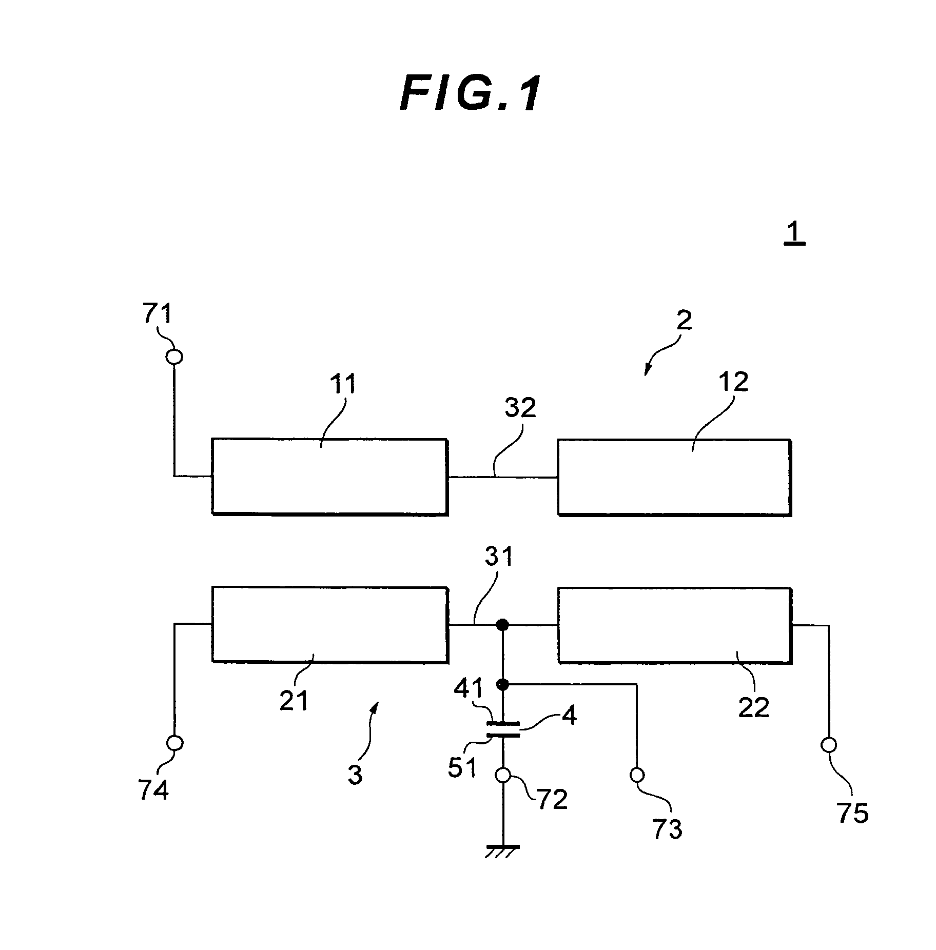
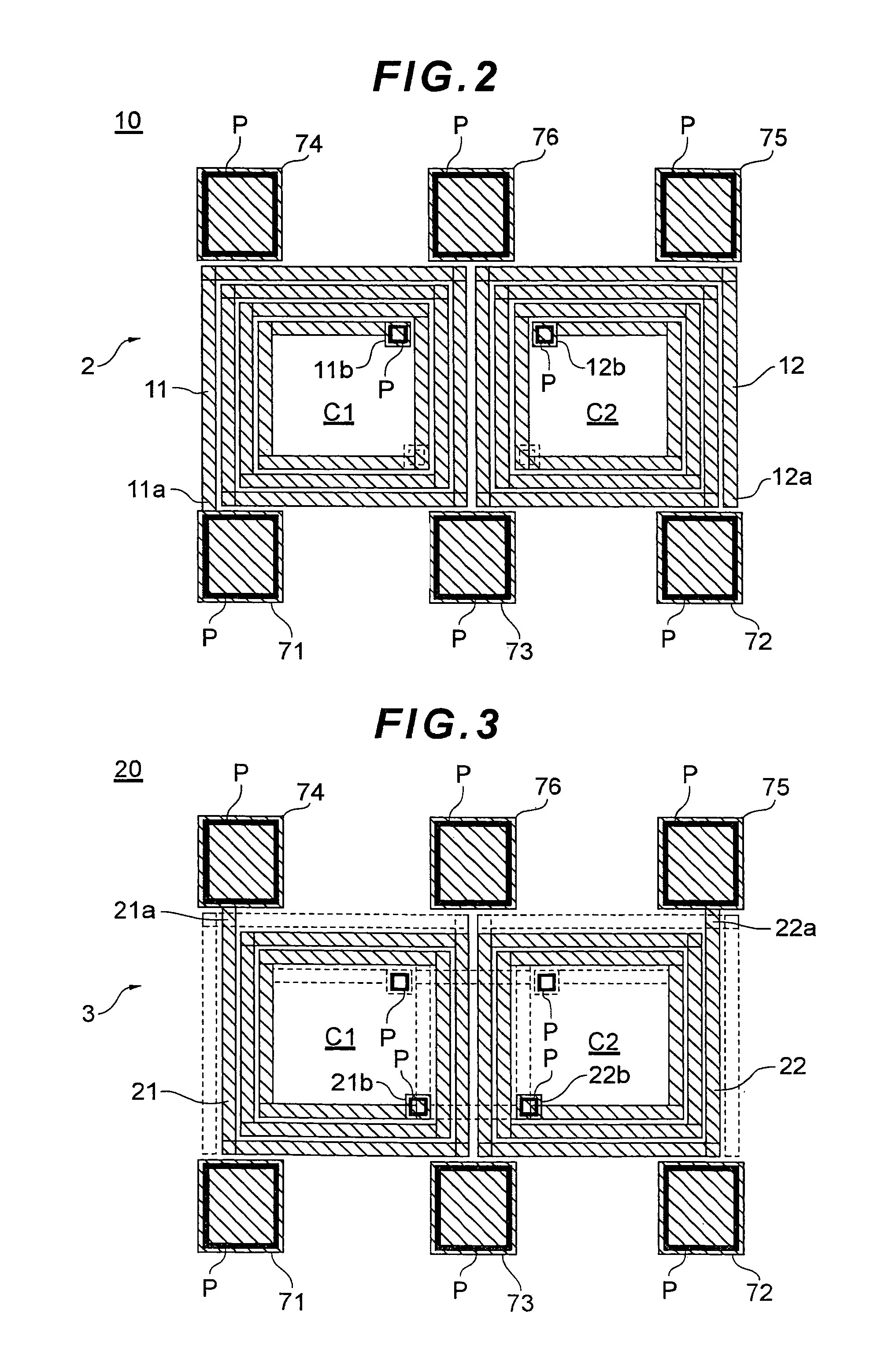
[0049]The structure illustrated in FIG. 7 in which the distance t1 from the coil 22 to the upper electrode 51 is set to 70 μm is Example 1. A layout of the respective wiring layers is as illustrated in FIGS. 2 to 6.

example 2

[0056]In Example 2, as illustrated in FIG. 10, an upper electrode 52 which extended from the region opposed to the lower electrode 41 to the region opposed to the two coil openings C1 and C2 was formed. The distance from the coils to the upper electrode was set to 70 μm as in Example 1.

[0057]In FIG. 11, a result obtained by calculating output balancing of two balanced signals with simulation is illustrated. Conditions are the same as those described with reference to FIG. 9. In FIG. 11, E2 indicates a result of Example 2 and C1 indicates a result of Comparative example 1.

[0058]As illustrated in FIG. 11, it is seen that, in Example 2 in which the upper electrode 52 is extended to the coil openings C1 and C2, although the balanced transmission characteristics are inferior to those in Example 1 in which the upper electrode 51 is disposed over the entire surface of the coil region, the balanced transmission characteristics are excellent compared with Comparative example 1.

[0059]Lastly, ...

example 3

[0060]In Example 3 illustrated in FIG. 12, lower electrodes 42a and 42b of the capacitor 4 are disposed to be symmetrical with respect to an imaginary line which divide the left and right coils into individual coils (equal to an imaginary line connecting the NC terminal 76 and the DC supply terminal 73). The lower electrodes 42a and 42b are arranged not to overlap the coil openings C1 and C2 but to overlap the coil conductors. The lower electrodes 42a and 42b are connected to each other by a leading wire 43.


PUM


Abstract

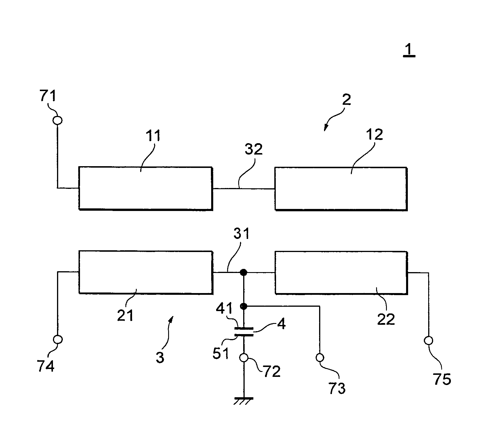
A thin film balun includes: an unbalanced transmission line which includes two coils; a balanced transmission line which includes two coils and is electromagnetically coupled to the unbalanced transmission line; a first electrode which is connected to the balanced transmission line and constitutes a capacitor; and a second electrode which is connected to a ground terminal and disposed to be opposed to the first electrode and constitutes the capacitor. The second electrode has a section opposed to the coils configuring the unbalanced transmission line or the balanced transmission line, the section being integrally formed with a section opposed to the first electrode.

Description

BACKGROUND OF THE INVENTION[0001]1. Field of the Invention[0002]The present invention relates to a balun that performs unbalanced-to-balanced signal conversion, and more particularly to a thin film balun formed by a thin film process which is advantageous for miniaturization and thickness reduction.[0003]2. Description of the Related Art[0004]Radio communication apparatuses include various high frequency elements such as antenna, filter, RF switch, power amplifier, RF-IC and balun. Here, resonant elements such as antenna and filter handle unbalanced signals relative to the ground potential; however, RF-IC, which produces or processes high frequency signals, handles balanced signals. Thus, in connecting the two types of elements, a balun is used which functions as an unbalanced-to-balanced signal converter.[0005]Sometimes a balanced signal needs to be amplified by applying a bias to a balun used in mobile communication equipment such as mobile-phone and wireless LAN. In this case, be...

Claims


Application Information

Patent Timeline
Patent Type & Authority Patents(United States)
IPC IPC(8): H03H7/42H01P3/08
CPCH03H7/42H01L23/5223H01L23/5225H01L23/5227H01P5/10H03H2001/0078H03H2001/0085H01L2924/0002H01L2924/00
Inventor ENDO, MAKOTO
Owner TDK CORPARATION
Learn More