
Atomic beam optical frequency atomic clock and a producing method thereof

a technology of optical frequency and atomic clock, which is applied in the direction of generating/distributing signals, instruments, horology, etc., can solve the problems of low inability to improve stability, and inability to achieve accuracy that may be achieved, so as to increase the signal-to-noise ratio and improve the detection efficiency of atoms

Active Publication Date: 2012-03-27
PEKING UNIV
View PDF6 Cites 4 Cited by
  • Summary
  • Abstract
  • Description
  • Claims
  • Application Information

AI Technical Summary

Benefits of technology

This approach improves atom detection efficiency to 100% and increases the signal-to-noise ratio, resulting in an atomic clock that is two orders of magnitude more stable and one order of magnitude more accurate than commercial cesium clocks.

Problems solved by technology

So far, all the atomic clocks of optical frequency based on a heated atomic beam technology are limited by the low signal-to-noise ratio of fluorescence signals with no exception, so that the stability can not be improved and the accuracy that may be achieved is also limited ultimately.
At present, the best accuracy that the atomic clock at optical frequency based on the calcium atomic beam may achieve is a little worse than that of a HP5071 small cesium clock so that it can not compete with the commercial HP5071 small cesium clock.
Such low detection efficiency for the atoms greatly limits the accuracy and the stability of the atomic clock that can be implemented.

Method used


Image

  • Atomic beam optical frequency atomic clock and a producing method thereof
  • Atomic beam optical frequency atomic clock and a producing method thereof
  • Atomic beam optical frequency atomic clock and a producing method thereof

Examples


Embodiment Construction

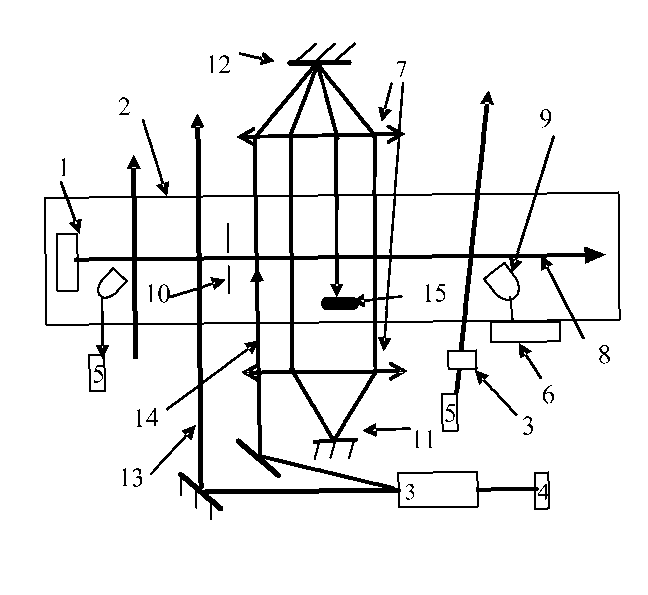
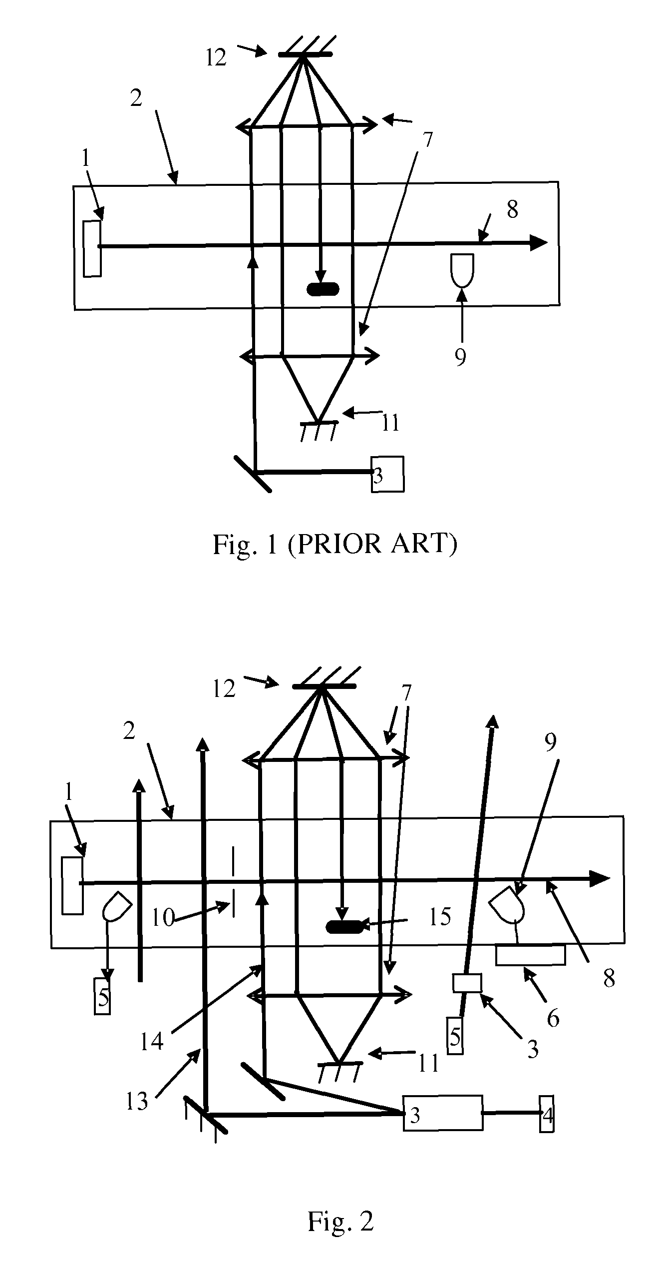
[0036]The atomic clock at optical frequency based on atomic beam in accordance with the present invention includes the following steps.

[0037]Atomic beam is ejected from a mouth of oven after heating an atomic oven in a vacuum chamber;

[0038]Laser corresponding to frequency of a clock transition transfers particles in the atomic beam from a ground state of the clock transition to an excited state of the clock transition operates in an adiabatic passing mode;

[0039]After interacting with the laser corresponding to the frequency of the clock transition in the form of single field or separate field, the atomic beam passes a signal detection region with a detection laser using electron shelving detection. The frequency of the detection laser corresponds to one strong transition spectral line related to a transition energy level of an atomic clock. After the particles in the atomic beam moves to the detection region and interacts with the detection laser, each of the atoms gives off a photo...


PUM


Abstract

An atomic clock at optical frequency based on atomic beam and a method for generating the atomic clock comprises: The atomic beam (8) is ejected from a pile mouth after heating an atomic pile (1) in a vacuum chamber (2); A laser (4) corresponding to frequency of a clock transition transfers the atomic beam (8) from a ground state of the clock transition to an excited state of the clock transition in a adiabatic passing mode; After interaction with the laser corresponding to the frequency of a clock transition, the atomic beam (8) passes a signal detection region with a detection laser (5), and after the interaction with the detection laser (5), each of the atoms gives off a photon of spontaneous emission; An emitted fluorescence photon signal from atoms which is excited by the detection laser (5) is explored; A clock laser (4) for exploring transition frequency of an atomic clock is modulated. The signal which is detected performs frequency locking for the frequency of the clock laser which is locked on the clock transition spectrum of the atoms so as to implement the atomic clock.

Description

CROSS-REFERENCE TO RELATED APPLICATION[0001]This application is a national phase of the international application No. PCT / CN2006 / 02501 filed on Sep. 22, 2006, which claims the priority benefit of China application No. 200510130745.0 filed on Dec. 27, 2005, the content of which is hereby incorporated by reference in its entirety.FIELD OF THE TECHNOLOGY[0002]The present invention relates to an atomic clock at optical frequency based on atomic beam, which belongs to a technology field of frequency standard at the optical frequency region.BACKGROUND OF THE INVENTION[0003]The principle of an miniature optical frequency standard based on traditional calcium atomic beam is that, when a calcium oven is heated up to a temperature around 700 centigrade, the heated calcium atomic beam is ejected from the calcium oven and passes a 657 nm laser traveling wave field generated by two pairs of cat eye devices which are parallel with equal interval orderly after collimation. A proper magnetic field ...

Claims


Application Information

Patent Timeline
Patent Type & Authority Patents(United States)
IPC IPC(8): H03L7/26H01S1/06H01S3/091
CPCG04F5/14
Inventor CHEN, JING-BIAO
Owner PEKING UNIV
Learn More