
Structure for dynamic livelock resolution with variable delay memory access queue

a dynamic livelock and memory access technology, applied in the direction of instruments, digital computers, computing, etc., can solve the problems of affecting the overall system design complexity, affecting the forward progress of execution, and affecting the design structur

Inactive Publication Date: 2012-03-06
IBM CORP
View PDF7 Cites 15 Cited by
  • Summary
  • Abstract
  • Description
  • Claims
  • Application Information

AI Technical Summary

Problems solved by technology

Superscalar instruction issue and speculative execution are two strategies that improve performance but also significantly increase overall system design complexity.
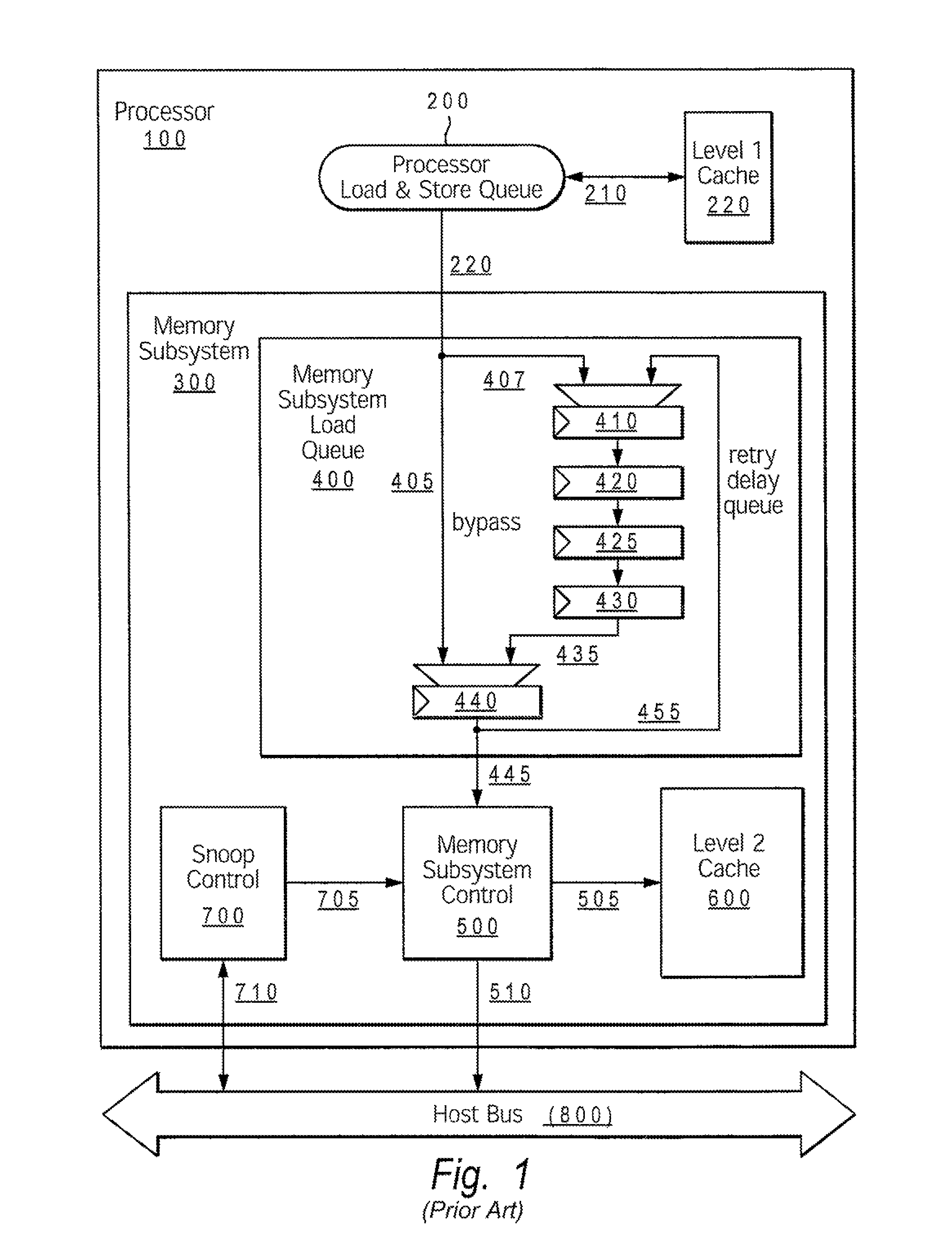
Occasionally, during instruction execution, a situation occurs whereby instructions are repeatedly issued, but a recurring transient conflict inhibits the forward progress of the execution of the instructions.
This condition is called a system livelock, and may be caused by any one of a number of conflict-generating instruction execution sequences.
With the addition of system bus interactions (e.g., snooped operations) and multiprocessor shared-memory architectures in conventional processing systems, the occurrences of livelocks are even more likely.
In conventional systems, system livelock is typically caused by one of the following conditions: (a) repeated flushing of instructions as a result of structural hazards that consequently cause the instructions to be speculatively refetched or repeatedly being re-issued from an issue queue; and (b) “harmonic” fixed-cycle interactions between multiple processing units, where one unit inhibits the forward progress of another.
This two step process then results in a harmonic livelock when certain conditions cause the above two step process to repeat indefinitely.
However, side effects of this enhancement include unexpected problematic circular conflicts.
Again, the ld C instruction bypasses the ld A instruction which has returned to the retry delay queue, and thus, continues to hinder the progress of ld A. A livelock occurs because instructions are repeatedly issued (st B, ld C) but the blockage of ld A caused by ld C prohibits the possibility of freeing store queue entries and thus, prohibits forward progress.
If the first thread's progress is dependent on a result from the second thread, the system will experience livelock because forward progress is impossible when the first thread repeatedly blocks the second thread.
The risk for livelocks is further increased when multiple processors share the same secondary memory system.
Livelock conditions are usually hard to predict and recreate and / or identify in simulation.
The software execution bugs that cause livelocks are often found later in the hardware validation process.
Breaking out of unanticipated livelock conditions presents a difficult challenge for the design of high performance microprocessors.
However, designs which include advanced livelock avoidance features may save significant test and redesign expenses.
However, none of these proposed methods resolves the different types / forms of livelocks in an efficient manner.

Method used


Image

  • Structure for dynamic livelock resolution with variable delay memory access queue
  • Structure for dynamic livelock resolution with variable delay memory access queue
  • Structure for dynamic livelock resolution with variable delay memory access queue

Examples


first embodiment

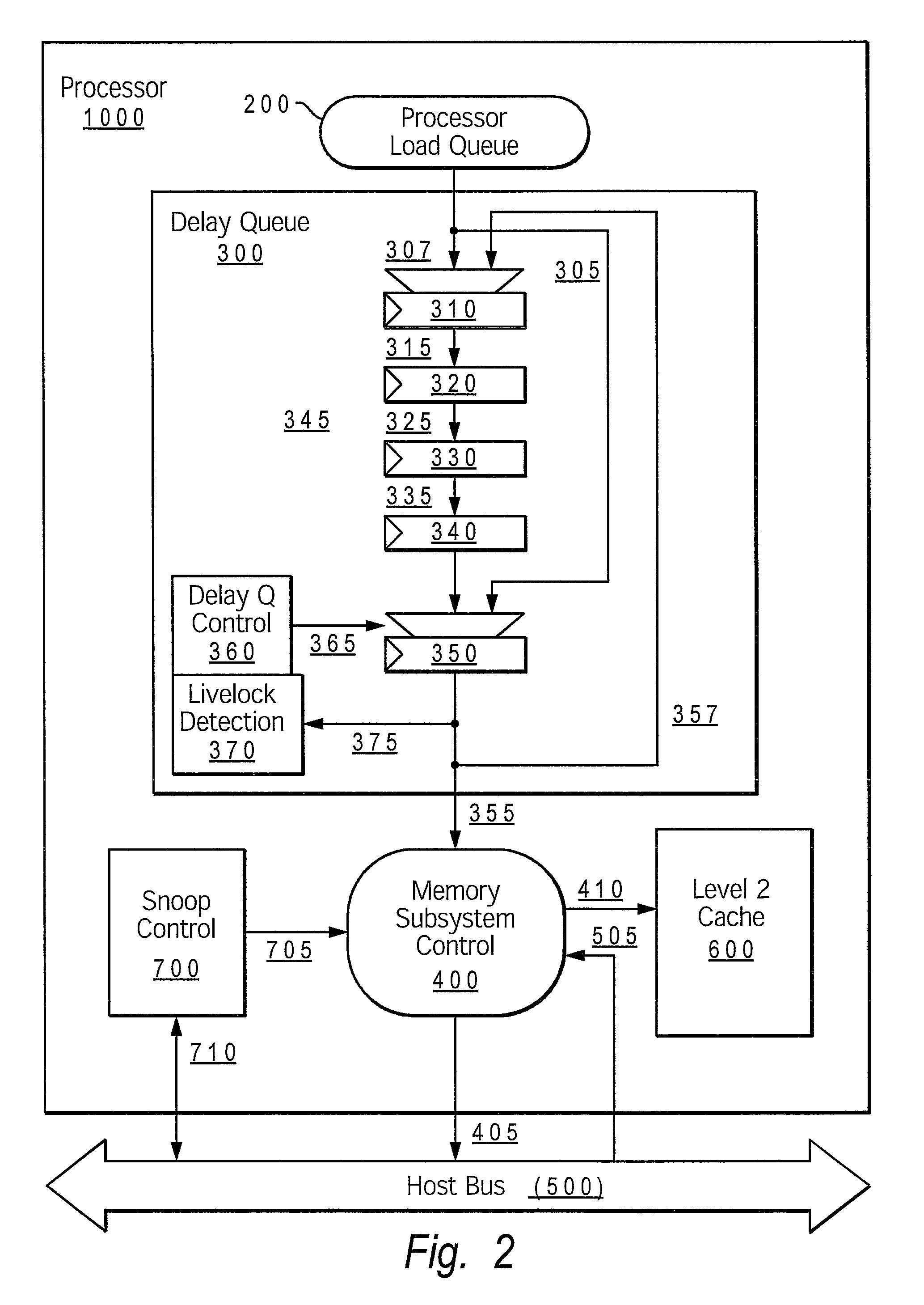
[0047]Turning now to the figures, FIG. 2 shows an example processing system configured with a livelock detection mechanism that provides the delay queue bypass disable method for resolving livelocks, according to the present invention. The processing system comprises processor core 1000, which includes processor load queue 200, delay queue 300 memory subsystem controller 400, snoop controller 700 and level 2 cache 600. Snoop controller 700 and memory subsystem controller 400 connect via respective paths 710 and 405 to host (or system) bus 500. Other memory structures within a memory subsystem (not shown) are connected to processor 1000 via host bus 500.

[0048]Delay queue 300 comprises delay path 345, which includes a series of delay stages 310, 320, 330, 340 (provided by latches), and final stage 350. Both first stage 310 and final stage 350 have an input MUX, utilized to select one of multiple possible inputs to the particular stage, as described below. Delay queue 300 also comprise...

second embodiment

[0051]FIG. 3 shows an example processing system configured with a livelock detection mechanism that provides the single step instruction method for resolving livelocks, according to the present invention. Structurally, FIG. 3 differs from FIG. 2 because of the inclusion of paths 306, 307 and 308 in FIG. 3. The livelock detection and resolution mechanisms may overlap with those illustrated within FIG. 2, and may also include additional / different functional logic to enable the variations of single step delay associated with the present method.

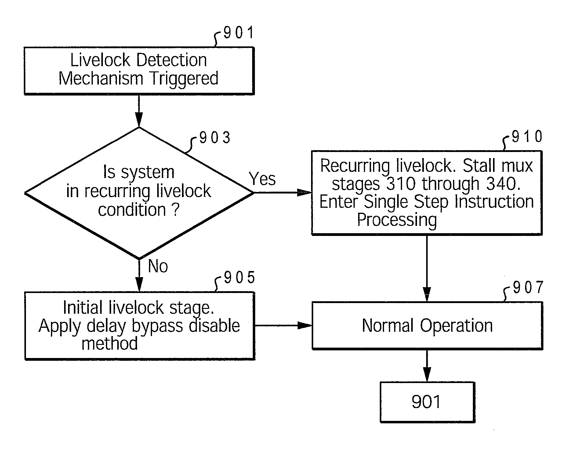
[0052]FIG. 3 shows how delay queue control 360 may also serve as instruction single step control as an alternative livelock breaking method. A livelock condition caused by snoop requests 705 from external bus 500 colliding with processor memory access requests 355 typically require adjustments beyond that of subtle sequencing modifications. When repeated collisions are not solved by the delay bypass disable mechanism (shown in FIG. 2), delay queu...


PUM


Abstract

A design structure for resolving the occurrence of livelock at the interface between the processor core and memory subsystem controller. Livelock is resolved by introducing a livelock detection mechanism (which includes livelock detection utility or logic) within the processor to detect a livelock condition and dynamically change the duration of the delay stage(s) in order to alter the “harmonic” fixed-cycle loop behavior. The livelock detection logic (LDL) counts the number of flushes a particular instruction takes or the number of times an instruction re-issues without completing. The LDL then compares that number to a preset threshold number. Based on the result of the comparison, the LDL triggers the implementation of one of two different livelock resolution processes. These processes include dynamically configuring the delay queue within the processor into one of two different configurations and changing the sequence and timing of handling memory access instructions, based on the specific configuration of the delay queue.

Description

PRIORITY CLAIM[0001]The present application is a continuation-in-part of U.S. patent application Ser. No. 11 / 530,612, titled “Dynamic Livelock Resolution with Variable Delay Memory Access Queue,” filed on Sep. 11, 2006. Benefit of priority is hereby claimed under 35 U.S.C. §120 to U.S. patent application Ser. No. 11 / 530,612, which is incorporated by reference herein in its entirety and for all purposes.BACKGROUND OF THE INVENTION[0002]1. Technical Field[0003]The present invention generally relates to design structures and in particular to design structures for dynamic livelock resolution in processor systems.[0004]2. Description of the Related Art[0005]To increase microprocessor performance, microarchitectures and memory subsystems employ a variety of techniques which allow multiple instructions to execute simultaneously. Superscalar instruction issue and speculative execution are two strategies that improve performance but also significantly increase overall system design complexit...

Claims


Application Information

Patent Timeline
Patent Type & Authority Patents(United States)
IPC IPC(8): G06F9/30G06F9/40G06F15/00
CPCG06F9/3824G06F9/3861G06F9/3842G06F12/0804
Inventor HALL, RONALDKARM, MICHAEL L.NG, ALVAN W.VENTON, TODD A.
Owner IBM CORP
Learn More