Eureka AIR delivers breakthrough ideas for toughest innovation challenges, trusted by R&D personnel around the world.

Pluggable power cell for an inverter

a power cell and inverter technology, applied in the direction of dc source parallel operation, electric device connection, coupling device connection, etc., can solve the problem of only limited number of series or parallel power cells, achieve high power building blocks, reduce cell foot print and weight, and increase cell power density

Active Publication Date: 2012-03-06
TECO WESTINGHOUSE MOTOR
View PDF41 Cites 46 Cited by
  • Summary
  • Abstract
  • Description
  • Claims
  • Application Information

AI Technical Summary

Benefits of technology

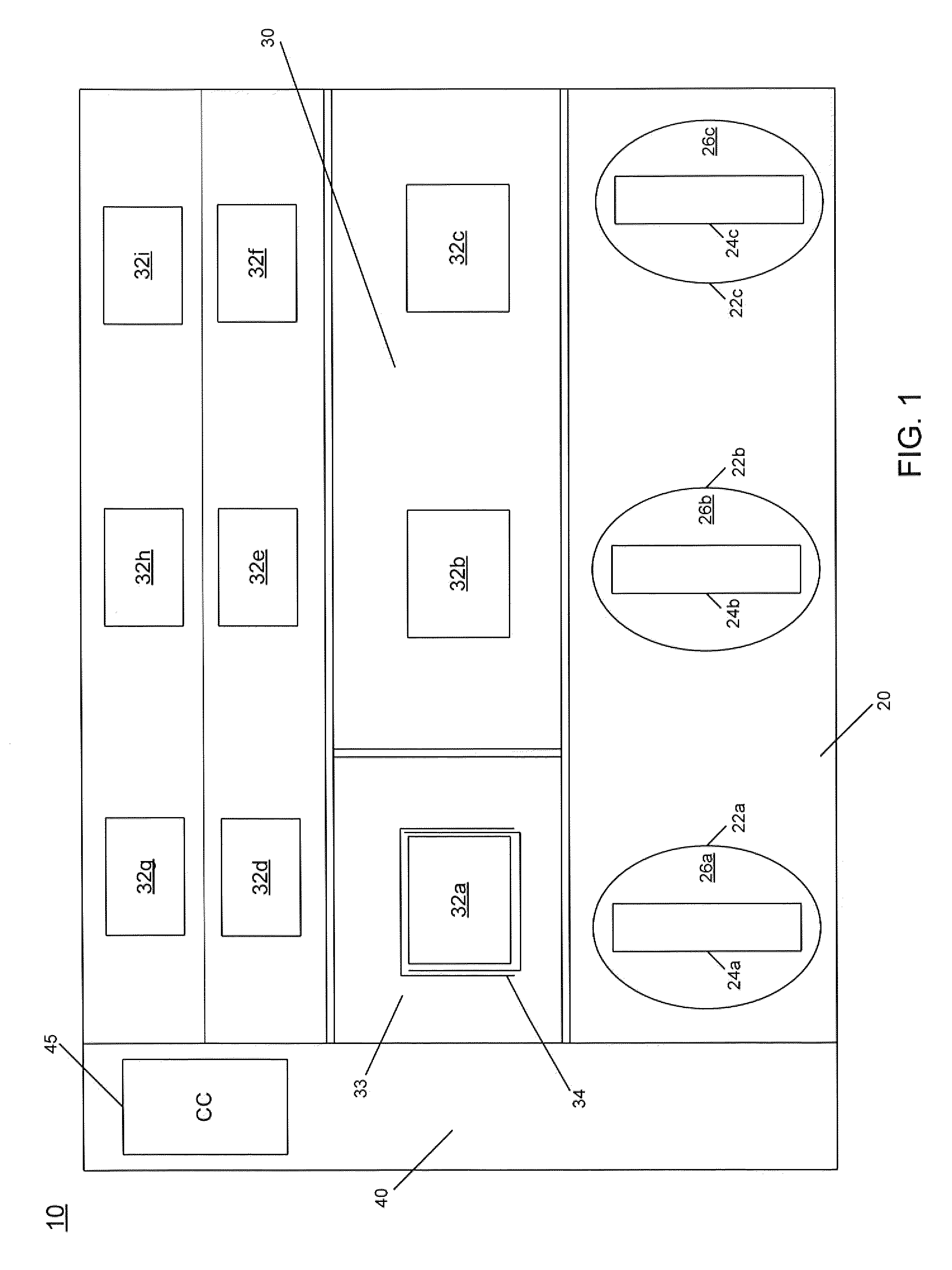
[0006]Embodiments introduce a cell integration method to reduce cell foot print and weight, and a method to increase the cell power density. In addition, embodiments provide a cell voltage isolation method to meet requirements up to several tens of kilovolts and provide a modular high power building block or cabinet configuration. This high power building block provides an efficient way to series and / or parallel power cells. The number of series or parallel power cells is only limited by the drive application. The cabinet configuration is based on a modular power transformer, small size pluggable power cell system, a reconfigurable electrical insulation method, and a master-slave control scheme. Embodiments provide overall system power and voltage scalability, standardized design, and easy reconfiguration to meet a wide power range in MW levels.
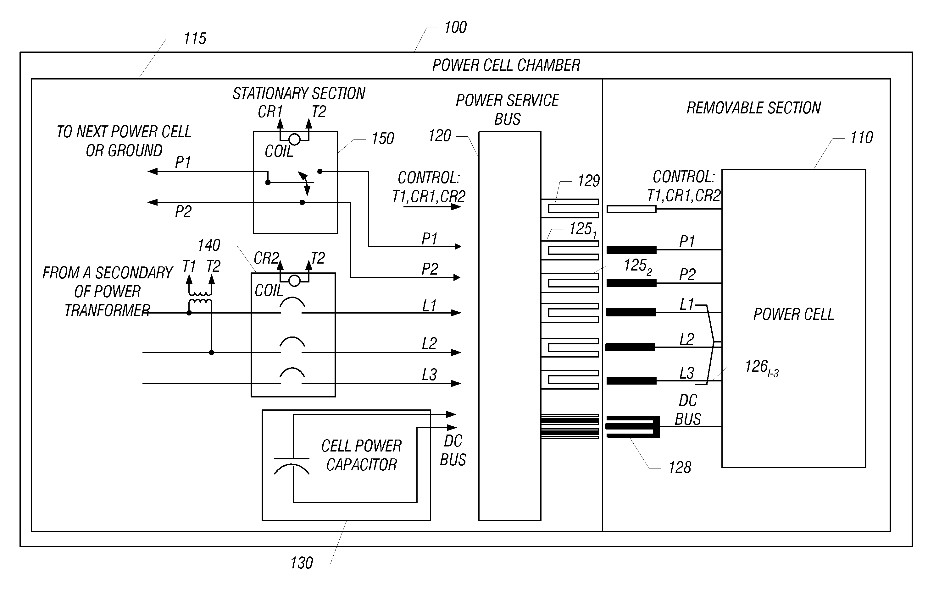
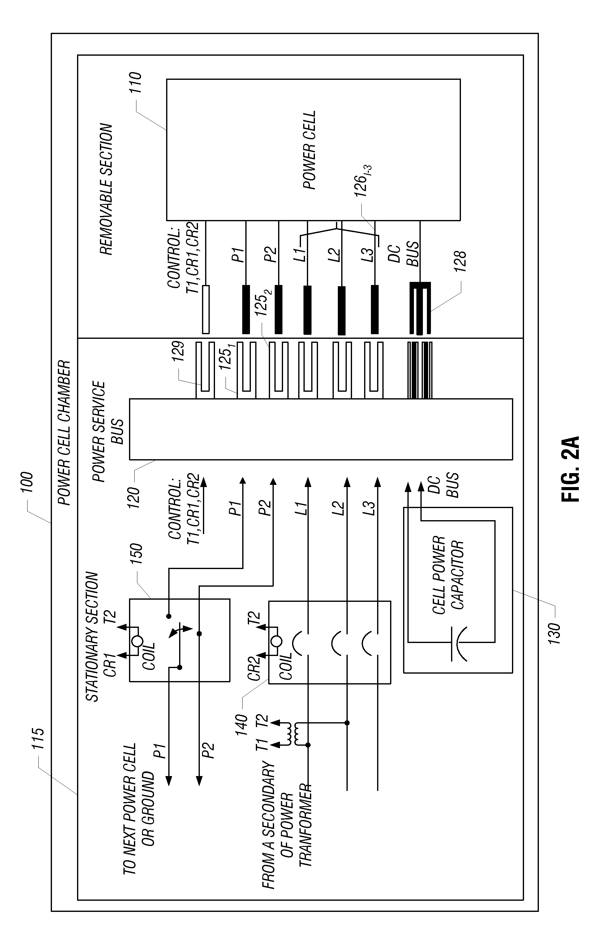
[0010]Yet another aspect of the present invention is directed to local low inductance bus capacitors coupled to a rectifier and inverter. Such capacitors may be of a removable portion of a power cell chamber. In turn, a power capacitor of the power cell chamber, which may be of a fixed portion of the power cell chamber, can provide a DC bus voltage to the removable portion. The local capacitors can be useable in a diagnostic mode in which the power capacitor is not available, and can further provide snubbing protection in a normal operation mode of a system including the power cell chamber.

Problems solved by technology

The number of series or parallel power cells is only limited by the drive application.

Method used


Image

  • Pluggable power cell for an inverter
  • Pluggable power cell for an inverter
  • Pluggable power cell for an inverter

Examples


Embodiment Construction

[0028]In various embodiments, a power cell chamber can be separated into multiple portions, namely a stationary or fixed portion and a moveable portion. These different portions may be joined by a power service bus. In this way, a module or other housing or enclosure that forms the moveable portion can be made to be relatively small and lightweight as compared to a conventional power cell. This allows for greater ease of customer access and removal, repair and replacement operations on these moveable portions of a power cell. In turn, the moveable portion may be plugged into a power service bus that couples the moveable portion with the fixed portion within the power cell chamber. The fixed portion of the chamber may include various components that would conventionally be present in a single power cell enclosure including, for example, a DC link by way of one or more capacitors. As such components can be relatively reliable over a number of years, these components present in the fix...


PUM


Abstract

In one embodiment, a power cell chamber for a drive system includes moveable and fixed portions. The moveable portion includes a rectifier stage to rectify an input signal received from a secondary winding of a transformer to provide a rectified signal and an inverter stage having a plurality of switching devices to receive a DC signal and output an AC signal. This moveable portion can be slidably adapted within a cabinet of the drive system. In turn, the fixed portion includes a DC link having at least one capacitor to receive the rectified signal and provide the DC signal to the inverter stage.

Description

BACKGROUND[0001]Generally, equipment referred to as a power converter, inverter or drive is used to provide power to another piece of equipment such as a motor. Specifically, such a converter (converter is used generally herein to refer to converters, inverters and drives) is coupled to a utility connection to receive incoming input power such as three-phase AC power. The converter conditions the power to provide a conditioned power to the equipment or load. In this way, incoming power to the load may be of improved efficiency, leading to reduced costs to operate the equipment.[0002]Multi-level power converters have been gaining popularity mainly due to improved input and output harmonics content, better electromagnetic compatibility, and higher voltage capability. These improvements in power conversion are achieved by using a multiple voltage step strategy. One common multi-level inverter topology is based on H-bridge inverters, in which multiple H-bridge inverters are connected in...

Claims


Application Information

Patent Timeline
Patent Type & Authority Patents(United States)
IPC IPC(8): H01H33/32H01R13/62
CPCH02M7/003H05K7/1432H02M7/49H05K7/14325H05K7/14
Inventor LEDEZMA, ENRIQUEKEISTER, THOMASABOLHASSANI, MEHDIEDWARDS, RYANSKORCZ, ALEXPIPHO, RANDALLSATUMAHANTI, SRINIVAS
Owner TECO WESTINGHOUSE MOTOR
Why Eureka
Eureka Blog
Learn More