Eureka AIR delivers breakthrough ideas for toughest innovation challenges, trusted by R&D personnel around the world.

Method and apparatus for treating a process volume with multiple electromagnetic generators

a generator and process volume technology, applied in the direction of electric/magnetic/electromagnetic heating, separation processes, magnetic separation, etc., can solve the problems of high cost and time consumption of extraction of oil from these materials, add as much as 15% to a barrel of oil at current prices, and achieve rapid adjustment and facilitate the effect of keeping the sources matched

Inactive Publication Date: 2012-03-06
RF THUMMIM TECH
View PDF65 Cites 14 Cited by
  • Summary
  • Abstract
  • Description
  • Claims
  • Application Information

AI Technical Summary

Benefits of technology

[0014]In the case of plasma formation, use of the circular geometry with appropriate transverse electric (denoted as TElmn) resonator modes allows confinement of a plasma to the axis of the reaction or process chamber, thus allowing more efficient heating of the reaction or process volume by applying a magnetic field that is transverse to the electric field and by additionally applying a radio frequency field. In addition, a static solenoidal field may be added to help confine the plasma to the resonator axis.
[0015]By operating the resonant structure in many spatial modes at once and by employing the unique structure herein disclosed, it is possible to apply more power by using more generators and to more uniformly excite the medium being acted upon along the length of the resonant structure.
[0017]It is therefore an object of the present invention to provide a method and apparatus to couple lower, radio frequency (RF) electromagnetic sources to the reaction and process volume in addition to the microwave sources. It is further an object of the present invention to provide for a static magnetic field. In order to accomplish this, the process or reaction chamber is arranged such that several microwave modes are simultaneously resonant in the structure. This permits more even and greater excitation of the material being processed or reacted upon.
[0018]It is another object of the present invention to allow several microwave inputs of the same or different frequencies. For the present invention, generators with the same frequency are locked in phase. Each generator is coupled to the appropriate resonant mode both mechanically and electronically match the resonant modes of the reaction or process chamber and to facilitate keeping the sources matched to the chamber when the load changes. This is especially important in the case where a plasma is established in the reaction chamber. In such a case, the load changes dramatically when a plasma forms. The present invention further provides electronic and mechanical tuning for matching of the microwave generators to the process or reaction chamber and allows rapid adjustment for maintaining matching to the load.

Problems solved by technology

Tar sands, oil sands and oil shales, contain large quantities of oil; however, extraction of oil from these materials is costly and time-consuming.
Pumping heavy oil from oil sands is difficult.
This adds a cost of as much as 15% to a barrel of oil at current prices.
Another problem that is becoming increasingly important is the disposal of toxic wastes.
A single mode resonant structure is smaller than a multimode resonant structure and cannot handle as much power input.
Matching and maintaining the electromagnetic generators and their respective delivery systems also is difficult in this configuration.
Prior art references also provide multiple generator inputs for a single mode resonant structure, but in the single mode configuration each generator would be required to have the same frequency and phase, and the resonant structure would limit how much power could be applied.
Further, in a microwave resonant structure, generally the plasma is not uniformly heated along the length of a process or reaction chamber.

Method used


Image

  • Method and apparatus for treating a process volume with multiple electromagnetic generators
  • Method and apparatus for treating a process volume with multiple electromagnetic generators
  • Method and apparatus for treating a process volume with multiple electromagnetic generators

Examples


Embodiment Construction

[0032]In the following description, reference is made to the accompanying drawings, which form a part hereof, and in which is shown, by way of illustration, various embodiments of the present invention. It is understood that other embodiments may be utilized and changes may be made without departing from the scope of the present invention.

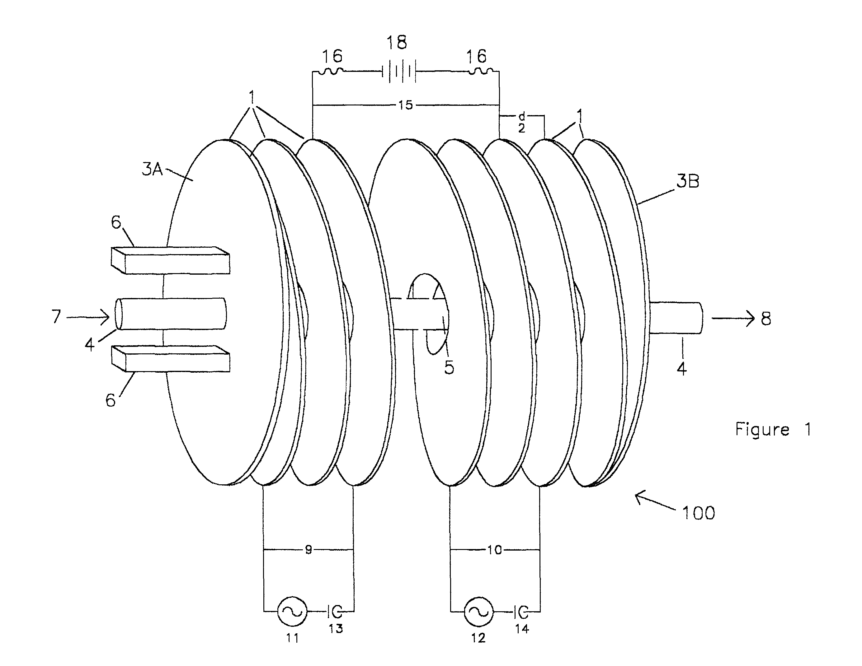
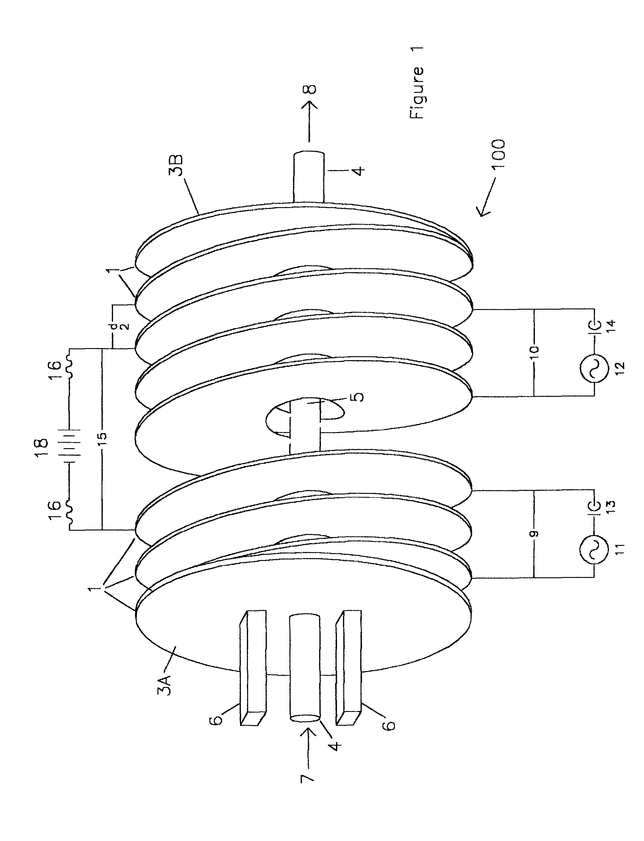
[0033]FIG. 1 shows the general concept of the invention. A resonant cavity at microwave frequencies (there may be several different microwave frequency inputs) is formed by a conducting, metal spiral 100. The inside diameter of the spiral is chosen to support the appropriate microwave modes of a cylindrical resonator 4 with diameter equal to the inside diameter of the spiral. The length is chosen to be an integral number of half wavelengths of the input microwave frequency. Multiple microwave and multiple RF sources 11, 12 deliver power to the resonant structure. While, generally speaking, it is not possible to have a microwave cavity resonant at a...


PUM

PropertyMeasurementUnit
frequencyaaaaaaaaaa
frequencyaaaaaaaaaa
electromagnetic radiationaaaaaaaaaa

Abstract

A method and apparatus are described that couples a plurality of electromagnetic sources to a material for the purpose of either processing the material or promoting a chemical reaction. The apparatus couples various electromagnetic sources of various frequencies, including provision for static magnetic fields, radio frequency fields, and microwave fields, with the possibility of applying them all simultaneously or in any combination.

Description

CROSS REFERENCE TO RELATED APPLICATION[0001]This application is a continuation-in-part of copending U.S. application Ser. No. 12 / 234,503, filed Sep. 19, 2008, the contents of which are incorporated herein by reference.FIELD OF THE INVENTION[0002]This invention relates generally to processing or reaction of materials. The invention has particular utility in the use of electromagnetic energy to promote a chemical process or reaction, such as the breaking of chemical bonds in large molecules and will be described in connection with such utility, although other utilities are contemplated. An example of this is to break molecular bonds in long hydrocarbon chains so that shorter chain and lower weight hydrocarbons are created. Such a process could for example reduce heavy, viscous oil to a less viscous consistency so that it can be more easily transported through a pipe.BACKGROUND OF THE INVENTION[0003]Petroleum-based materials are integral to the world's economy and demand for petroleum ...

Claims


Application Information

Patent Timeline
Patent Type & Authority Patents(United States)
IPC IPC(8): C07C2/00C07C4/00C07C5/00C07C6/00B01J19/08
CPCB01D17/0205B01J19/088B01J19/126B01J19/129B03C1/0335B03C1/30H05B6/6488H05B6/806B01J2219/083B01J2219/0854B01J2219/0862B01J2219/0877B01J2219/0894B01J2219/1227B01J2219/1269B01J2219/1296
Inventor PROUDKII, VASSILLI P.MCNEIL, KIRKYARBOROUGH, JOE MICHAEL
Owner RF THUMMIM TECH
Why Eureka
Eureka Blog
Learn More