
Filter for removing sediment from water

a filter and sediment technology, applied in the field of sedimentation filter elements, can solve the problems of clogging fish gills, major source of water pollution, and sediment pollution, and achieve the effect of reducing the number of sediment particles, and improving the quality of sedimen

Active Publication Date: 2012-02-28
CONTECH ENGINEERED SOLUTIONS
View PDF103 Cites 57 Cited by
  • Summary
  • Abstract
  • Description
  • Claims
  • Application Information

AI Technical Summary

Benefits of technology

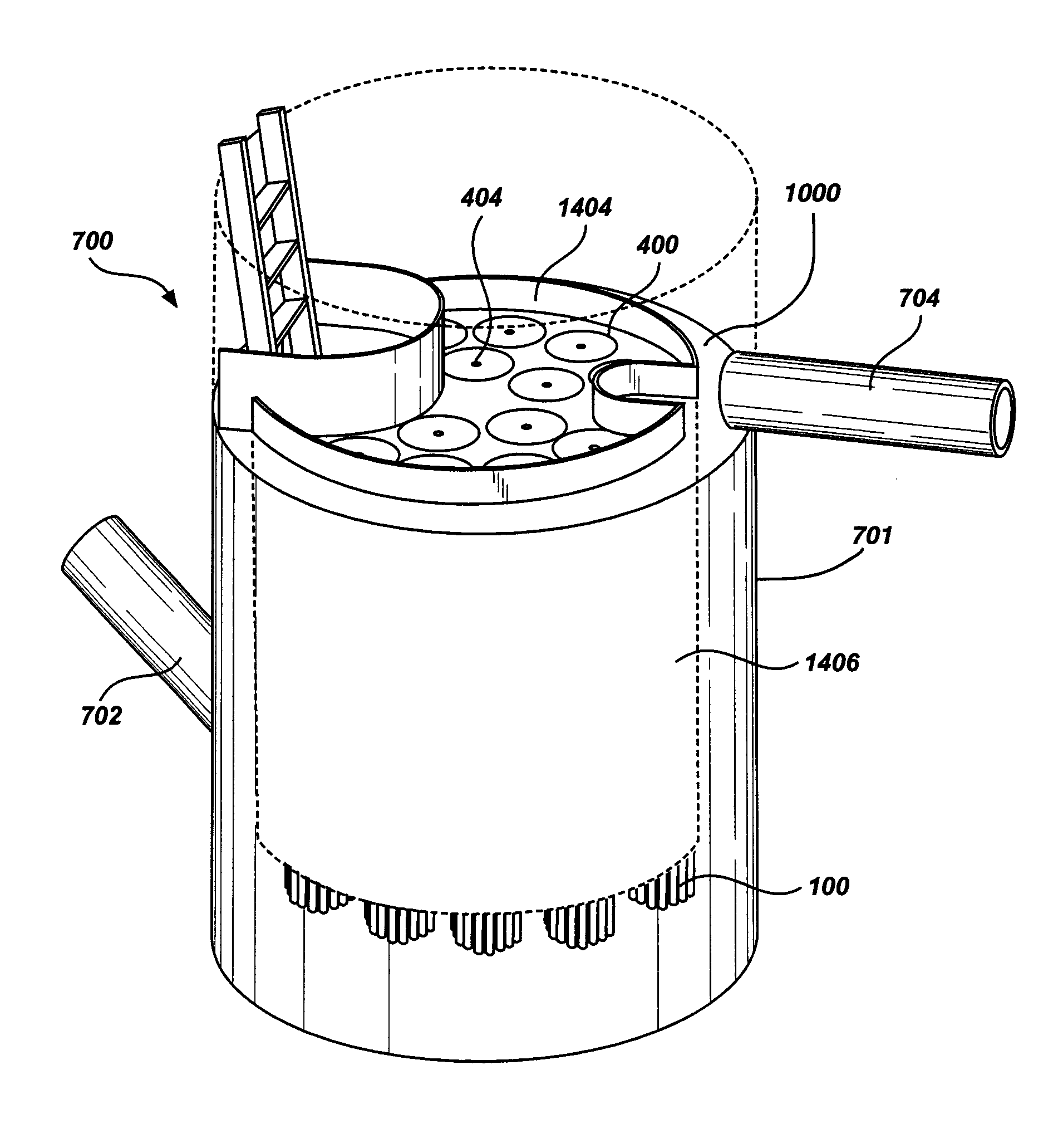
The present invention is a system for removing sediment from water. The system includes a filter chamber with a deck that divides the chamber into an upper and lower chamber, each chamber having holes for receiving a filtration element. The system also has an inlet line for introducing the influent liquid into the filter chamber, which is positioned tangentially to the chamber. The system may also include a ridge or skirt positioned on the deck to improve the filtration process. The technical effects of the invention include improved sediment removal from water and a more efficient filtration process.

Problems solved by technology

Stormwater runoff does not usually receive any treatment before it enters streams, lakes, and other surface waters, and it is a major source of water pollution.
One of the harmful pollutants of major concern is sediment.
Sediment accumulates in water bodies and destroys feeding grounds for aquatic life, clogs fish gills, blocks light, increases water temperature, and can cause other adverse environmental impacts.
Sedimentation-based tanks, however, cannot completely remove all of the fine sediment from stormwater because of the required settling time needed for fine sediment to be removed from stormwater.
For example, settling out the fine sediment in stormwater would require a large and uneconomical sedimentation-based tank.
However, as the fine sediment continues to accumulate, the interstitial gaps eventually clog and must be frequently recharged.
Granular media filter systems can be partially recharged through pressurized backwashing, but pressurized backwashing piping and controls are complicated and expensive.
While these types of filters and others like them have their merits, they also have their drawbacks.
As a result, during high flow events, the filter systems quickly clog, causing the stormwater runoff to back up.

Method used


Image

  • Filter for removing sediment from water
  • Filter for removing sediment from water
  • Filter for removing sediment from water

Examples


example

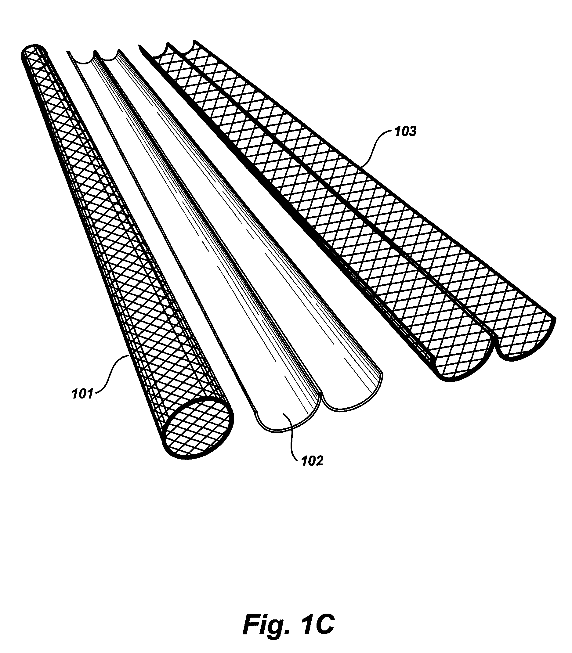
[0092]An experiment was conducted using five filtration cartridges, each having eighteen elongated filtratable elements, for a total of 90 elements. Each elongated filtratable element was constructed by wrapping filter mats around a flexible inner core, and enclosing the filter mats in a nylon screen. Each filtratable element was 0.75″ in diameter and 48″ long. The elongated filtratable elements tested had a surface area of about 90 square feet. The filtration cartridges were placed inside a 3′ diameter filtration chamber. With less then 5 inches of headloss, the prototype filtration system was able to remove over 5 kg of sil-co-sil 106 (a standard fine sediment mixture) from the influent water having a flow rate of 1 L / s and a sediment concentration of 300 mg / L. The filter cartridge occupied approximately 1 square foot of area in an impermeable deck separating the unfiltered and filtered water. The effluent water stream had a sediment content less than 20% of the influent concentra...


PUM

PropertyMeasurementUnit
surface areaaaaaaaaaaa
concentrationaaaaaaaaaa
flow rateaaaaaaaaaa

Abstract

A system for removing sediment from water is disclosed. The exemplary embodiments described herein disclose a system comprising a filter chamber, having a deck positioned inside to divide it into an upper chamber and a lower chamber. The deck may have a plurality of holes to hold filtration elements and also may have a ridge or a skirt or both. An inlet line may be tangentially connected to the filter chamber and introduce influent liquid into the filter chamber below the deck and outside of the skirt.

Description

[0001]This is a continuation-in-part of U.S. patent application Ser. No. 11 / 839,303, which was filed on Aug. 15, 2007 and entitled “FILTER FOR REMOVING SEDIMENT FROM WATER,” the disclosure of which is incorporated by reference.BACKGROUND OF THE INVENTION[0002]1. Field of the Invention[0003]The present invention generally relates to an apparatus, system, and method for removing sediment from water, and, more particularly, to an elongated filtratable element used for removing sediment from stormwater.[0004]2. Description of the Related Art[0005]Stormwater runoff is rainfall or snowmelt that travels over the ground or impervious surfaces—roofs of buildings, homes and sheds, roadways, parking lots, sidewalks and driveways—and drains into natural or manmade drainage ways. In some cases, stormwater runoff drains directly into bodies of water. Stormwater runoff does not usually receive any treatment before it enters streams, lakes, and other surface waters, and it is a major source of wate...

Claims


Application Information

Patent Timeline
Patent Type & Authority Patents(United States)
IPC IPC(8): B01D29/66B01D29/52C02F1/00
CPCB01D29/114B01D35/10B01D21/2411B01D21/0012E03F5/14B01D29/15B01D29/52B01D29/66B01D29/72B01D29/74B01D2201/0461B01D2201/0446B01D2221/12B01D27/08B01D27/14B01D35/20B01D35/30
Inventor MURRAY, CHRISTOPHER ADAMLAWLESS, DARREN FRANCIS KEVINWILLIAMS, GREGORY RICHARDBRAUN, STEPHEN ERICGARBON, JOEL ANTHONY
Owner CONTECH ENGINEERED SOLUTIONS
Learn More