Electric power steering device

a technology of electric power steering and steering shaft, which is applied in the direction of steering initiation, instruments, special purpose vessels, etc., can solve the problems of significant change in the assist power of the motor, significant change in the steering characteristics of the eps, and inevitably deterioration of the steering feeling, so as to improve the steering feeling, reduce the oscillation, and smooth the effect of the motor rotation

Inactive Publication Date: 2012-02-14
JTEKT CORP
View PDF13 Cites 13 Cited by
  • Summary
  • Abstract
  • Description
  • Claims
  • Application Information

AI Technical Summary

Benefits of technology

[0014]When rotation of the motor is smoothed by controlling the occurrence of the inverse assist torque using “phase deviation” due to the correction of the rotational angle, the achieved effects are maximized when the rotational angle correction amount is optimal. However, when the excess or deficiency in the rotational angle correction amount occurs, that is, when the rotational angle correction amount deviates from the optimum value, the advantageous effects are reduced as the deviation increases. When the deviation further increases, there is a possibility that the inverse assist torque occurs that, contrary to the original object, impedes smooth rotation of the motor. Thus, it is very difficult to previously set the correction amount so that the rotational angle correction amount is always optimum.
[0015]According to the above configuration, however, the unsmooth rotation due to the lack of the correction amount is avoided by setting a relatively large value (absolute value) having a margin as the initial value of the rotational angle correction amount, and when the oscillation the level of which is high enough to affect the steering feeling, the rotational angle correction amount that is highly probable to have caused the occurrence of the oscillation is reduced, whereby the oscillation can be reduced. As a result, it is made possible to further smooth rotation of the motor and realize better steering feeling with a simple configuration.
[0016]The reduction of the amount of correction may be performed when the rotational angular speed of the motor is equal to or higher than a predetermined speed. Specifically, when the rotational angular speed of the motor is equal to or lower than the critical speed required for the motor to pass the deceleration section and the amount of correction of the rotational angle is reduced, the inverse assist performed when the inverse rotation as described above occurs can fall short, which can result in the occurrence of the stuck steering wheel. According to the above configuration, it is possible to further ensure the effect of suppressing the stuck steering wheel by the inverse assist while suppressing the oscillation due to the intentional generation of the inverse assist torque.
[0017]The motor control signal output part may reduce the amount of correction of the rotational angle inversely proportionally to the level of the oscillation when the level of the oscillation exceeds the predetermined level.
[0018]According to the above configuration, it is possible to more effectively reduce the oscillation due to the inverse assist torque. The oscillation detection part may determine the level of the oscillation based on the variation of the rotational angle that occurs during the time period from when the sign of the rotational angle is inverted to when the sign is again inverted.
[0019]According to the above configuration, even when the amplitude of the oscillation is not uniform or when a so-called whirling occurs, it is possible to accurately determine the level (magnitude) of the occurring oscillation. As a result, it is made possible to prevent erroneous operation of the stuck steering wheel suppression control and more effectively suppress the oscillation.

Problems solved by technology

However, the steering characteristics of the EPS change significantly due to the discontinuation of the motor control.
However, in the case described above in which an electrification failure occurs in a phase and therefore the motor control is continued with the other two electrification phases, deterioration of steering feeling occurs inevitably due to the occurrence of a torque ripple, in a configuration where a sinusoidal waveform current is applied to each electrification phase, as shown in FIG. 29 (in the illustrated example, the U phase is abnormal, and V and W phases are electrified).
In other words, because a motor current corresponding to a requested torque is not generated, the motor is continuously driven without delivering its true output performance, causing a significant change in the assist power of the motor.

Method used


Image

  • Electric power steering device
  • Electric power steering device
  • Electric power steering device

Examples


first embodiment

[0053]An electric power steering device (EPS) according to the invention is described hereinafter with reference to the drawings.

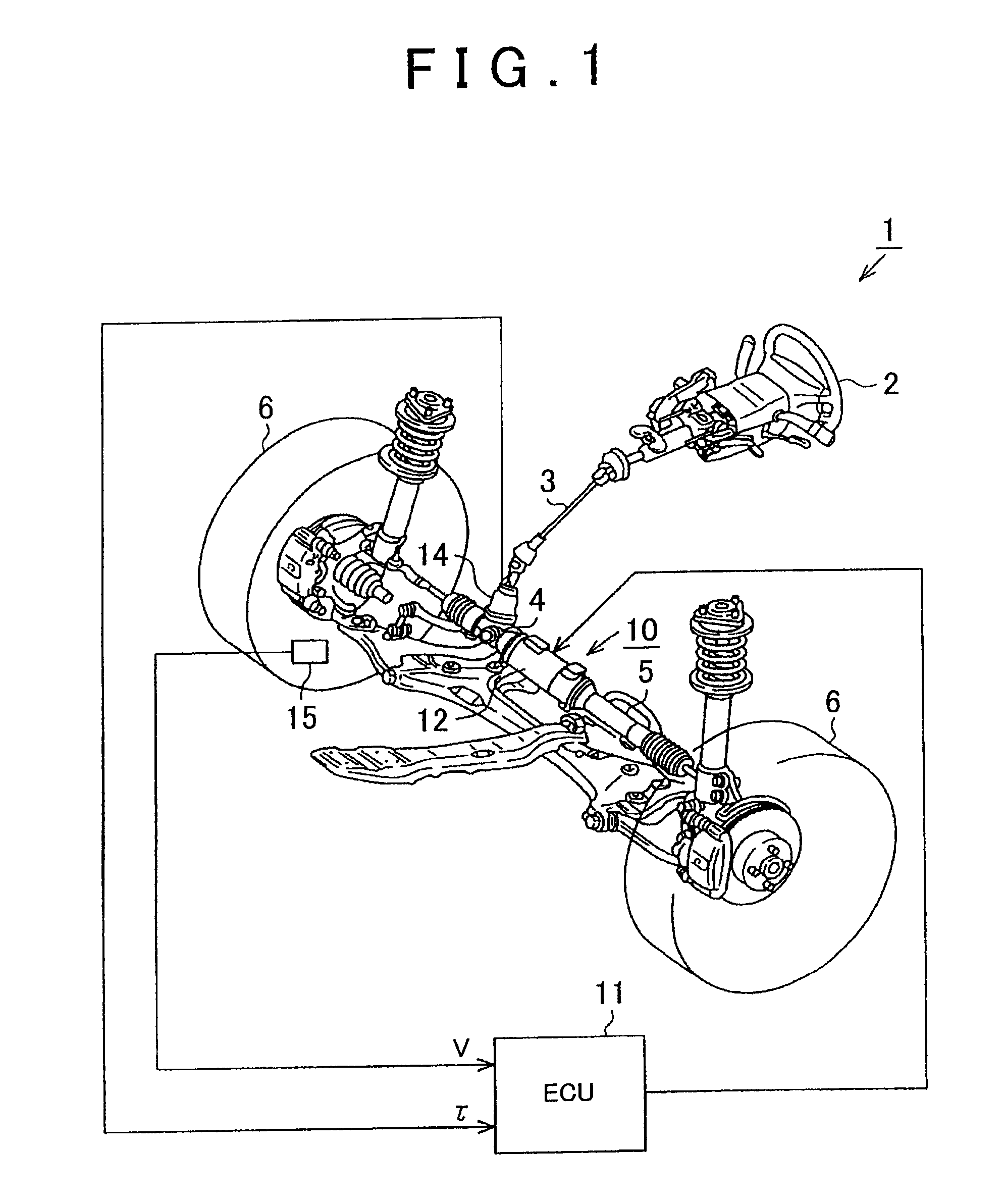
[0054]FIG. 1 is a schematic configuration diagram of an EPS 1 according to the first embodiment. As shown in the diagram, a steering shaft 3 connected to a steering wheel (steering) 2 is connected to a rack 5 via a rack-and-pinion mechanism 4. When a steering operation is performed, the rotation of the steering shaft 3 is converted into a linear motion of the rack 5 by the rack-and-pinion mechanism 4. Then, the linear motion of the rack 5 changes the steering angle of a turning wheel 6.

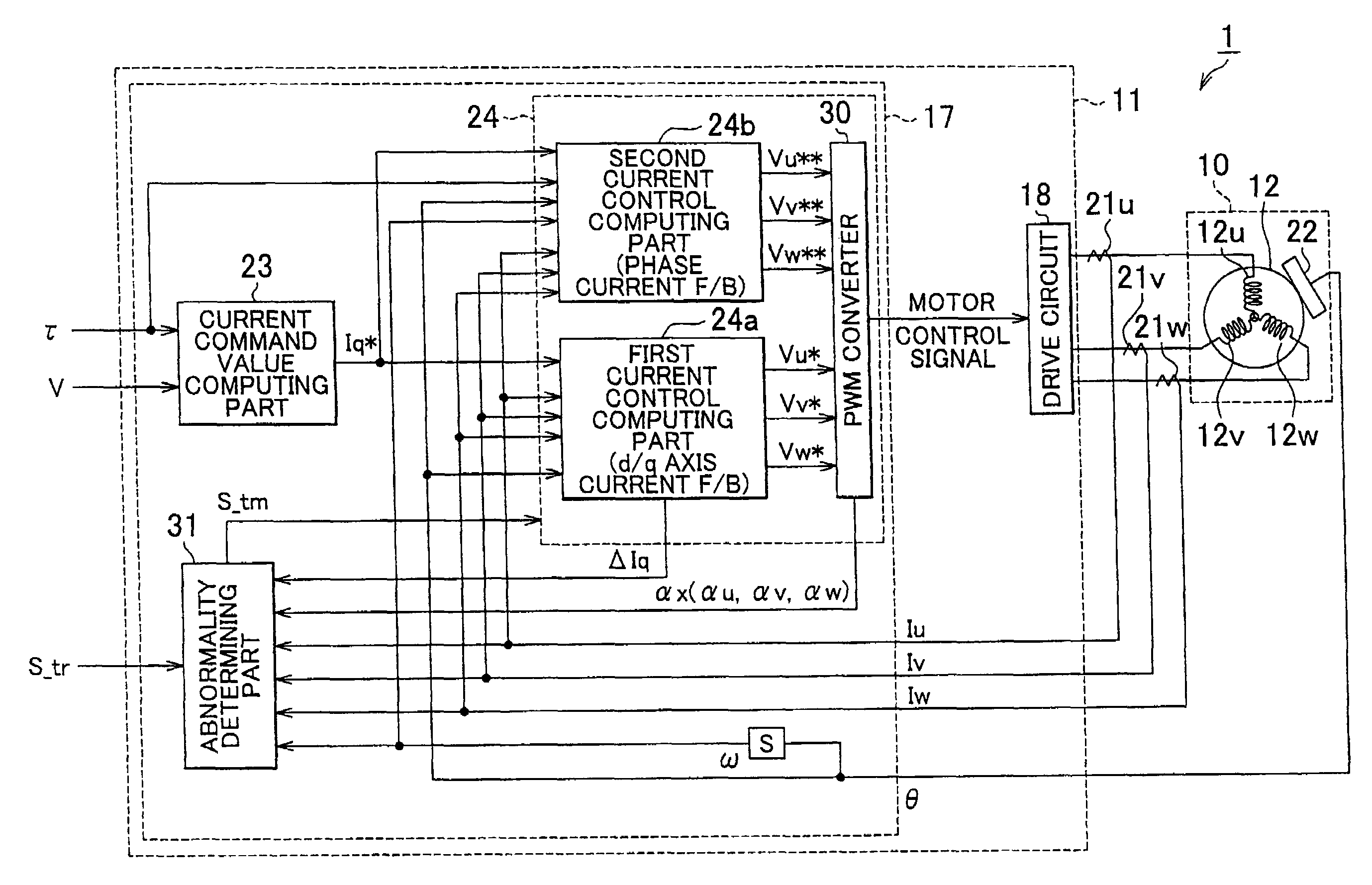
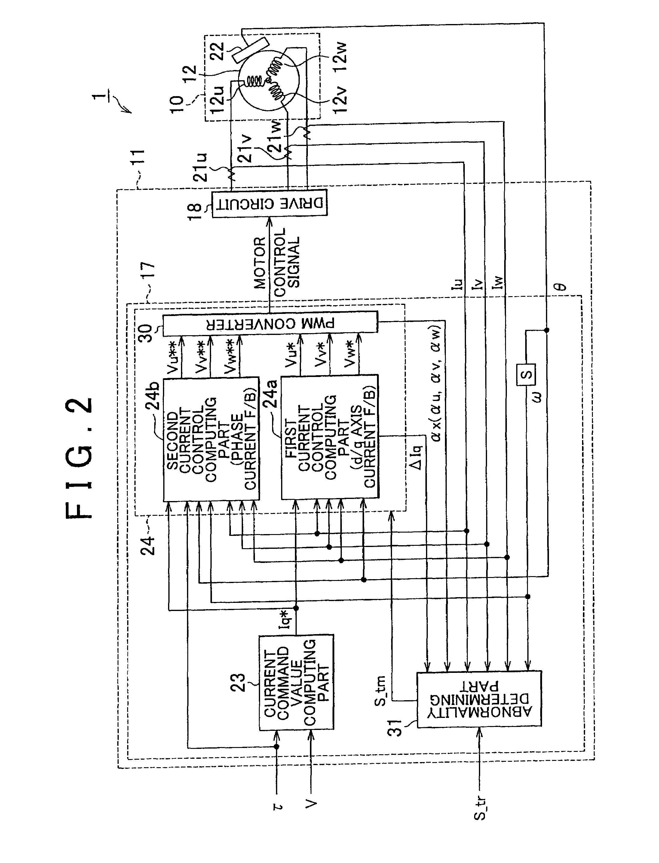
[0055]The EPS 1 has an EPS actuator 10 which functions as a steering force assisting device for applying an assist power to a steering system to assist its steering operation, and an electrical control unit (ECU) 11, which serves as the control means, for controlling actuation of the EPS actuator 10.

[0056]The EPS actuator 10 of this embodiment is a so-called rack-type EPS ac...

second embodiment

[0168]An electric power steering system is described hereinafter with reference to the drawings.

[0169]A major difference between this embodiment and the above-described first embodiment exists in the mode of the rotational angle correction control during two phase drive. Therefore, for convenience of explanation, the same reference numerals are used for the parts the same as those of the first embodiment, and the explanation of these parts are omitted.

[0170]As shown in FIG. 20, a rotational angle correction controller 50 of this embodiment is provided with an inverse assist correction amount computing part 51 instead of the first and second correction amount computing parts 41 and 42 (see FIG. 9) in the rotational angle correction controller 40 of the first embodiment.

[0171]In this embodiment, the inverse assist correction amount computing part 51 receives the steering torque τ, and the rotational angle θ and the rotational angular velocity ω of the motor 12. The inverse assist cor...


PUM


Abstract

A rotational angle correction controller controls generation of an inverse assist torque using the “phase deviation” due to the correction of the rotational angle θ, thereby performing the rotational angle correction control to smooth rotation of the motor during two phase drive. In addition, the rotational angle correction controller includes an oscillation detection part that detects the occurrence of oscillation in the steering system. When the level of the detected oscillation exceeds the predetermined level, the correction amount in the rotational angle correction control is reduced.

Description

INCORPORATION BY REFERENCE[0001]The disclosure of Japanese Patent Application No. 2008-007107 filed on Jan. 16, 2008 and Japanese Patent Application No. 2008-061489 filed on Mar. 11, 2008 including the specification, drawings and abstract is incorporated herein by reference in its entirety.BACKGROUND OF THE INVENTION[0002]1. Field of the Invention[0003]This invention relates to an electric power steering device.[0004]2. Description of the Related Art[0005]Many of the motor control devices that are used in electric power steering devices (EPS) and the like are provided with abnormality detecting means that detects an abnormality when an electrification failure occurs in any of the three phases (any of U, V and W phases) of a motor due to disconnection of a power supply line or a contact failure of a drive circuit. Upon detection of the abnormality, these motor control devices stop the motor control promptly to attain fail safe.[0006]However, the steering characteristics of the EPS ch...

Claims


Application Information

Patent Timeline
Patent Type & Authority Patents(United States)
IPC IPC(8): A01B69/00G05D1/00B63H25/04B62D12/00B62D11/00B62D6/00B63G8/20
CPCB62D5/0472B62D5/0484B62D5/0487
Inventor NOZAWA, TETSUYA
Owner JTEKT CORP
Why Eureka
Try Eureka