
Gas regulating and safety valve for burners of a modulatable gas heating device

a heating device and modulable gas technology, applied in the direction of lighting and heating apparatus, fluid pressure control, instruments, etc., can solve the problems of limiting the mechanical efficiency of the actuator of the gas valve, two actuators operating independently, and increasing the failure rate, so as to improve the operation reliability, the effect of reducing the failure ra

Inactive Publication Date: 2012-01-24
SAIA BURGESS DRESDEN
View PDF43 Cites 14 Cited by
  • Summary
  • Abstract
  • Description
  • Claims
  • Application Information

AI Technical Summary

Benefits of technology

[0013]The major advantage of the invention compared to the state of the art is that the two closure elements are completely mechanically decoupled from one another. In addition, greater actuating forces can be attained by eliminating a gas-tight sealing sleeve in the air gap of the linear drive and / or the electromagnet. By eliminating the gas-tight isolation sleeve, the current-carrying components, in particular the field winding of the electric motor implemented as a stepper motor of the first closure element and the field winding of the armature of the second closure element, are located within the gas flow. Practical experiments have shown that the gas control and safety valve of the invention is capable of operating with up to 30% greater actuating forces, which also improves operational reliability. Stated differently, the gas control and safety valve can be sized more economically while providing the same force.
[0014]In a particularly advantageous embodiment of the invention, the housing is formed in two parts with a first housing part and a second hosting part, wherein the first closure element is disposed in the first housing part and the second closure element is disposed in the second housing part. Preferably, the housing is cylindrical, whereby the inlet channel and the inlet chamber are located at a first end face, and the outlet channel is located at the other end face. To produce the gas control and safety valve, the two housing parts are typically connected so that the walls at the end faces of the two housing parts contact each other and are sealed against each other by using a sealing element.
[0015]The armature of the second closure element can be produced either as a solid armature or as a hollow armature. An armature implemented as a hollow armature is hereby arranged in the cylindrical cavity so as to operate against the force of the second spring element disposed inside the hollow armature. Conversely, when using a solid armature, the second spring element engages on the outside of the solid armature.
[0016]According to the invention, the spindle-nut system may be arranged either inside the electric motor or outside the electric motor. In the first case, the nut or the rotor, respectively, are driven by the field winding of the motor, whereby the spindle is formed as the drive axle. In the second case, the nut is driven by the motor shaft.
[0017]The spaced-apart axes of the two controllable closure elements may be arranged in the housing with any orientation; preferably, however, orthogonally as a corner valve, parallel or axially one after the other on a straight line.
[0018]When the gas control and safety valve has closure elements arranged consecutively on a straight line in the axial direction, an ondular washer is provided which is disposed on the housing wall in a sandwich structure between the opposing end faces of the two closure elements for the purpose of compensating for axial tolerances as well as for ensuring an adequate pressing force of the two closure elements.

Problems solved by technology

This invention has the disadvantage that both valve disks can only be opened together, thereby preventing the two actuators from operating independently.
Disadvantageously, due to the large number of components, conventional gas valves have large tolerance chains or interfering actuating paths which require a complicated installation and may also increase the failure rate.
Another major disadvantage of conventional gas valves is that the sealing sleeve required for external gas-tightness limits the mechanical efficiency of the actuators of the gas valves.

Method used


Image

  • Gas regulating and safety valve for burners of a modulatable gas heating device
  • Gas regulating and safety valve for burners of a modulatable gas heating device
  • Gas regulating and safety valve for burners of a modulatable gas heating device

Examples


Embodiment Construction

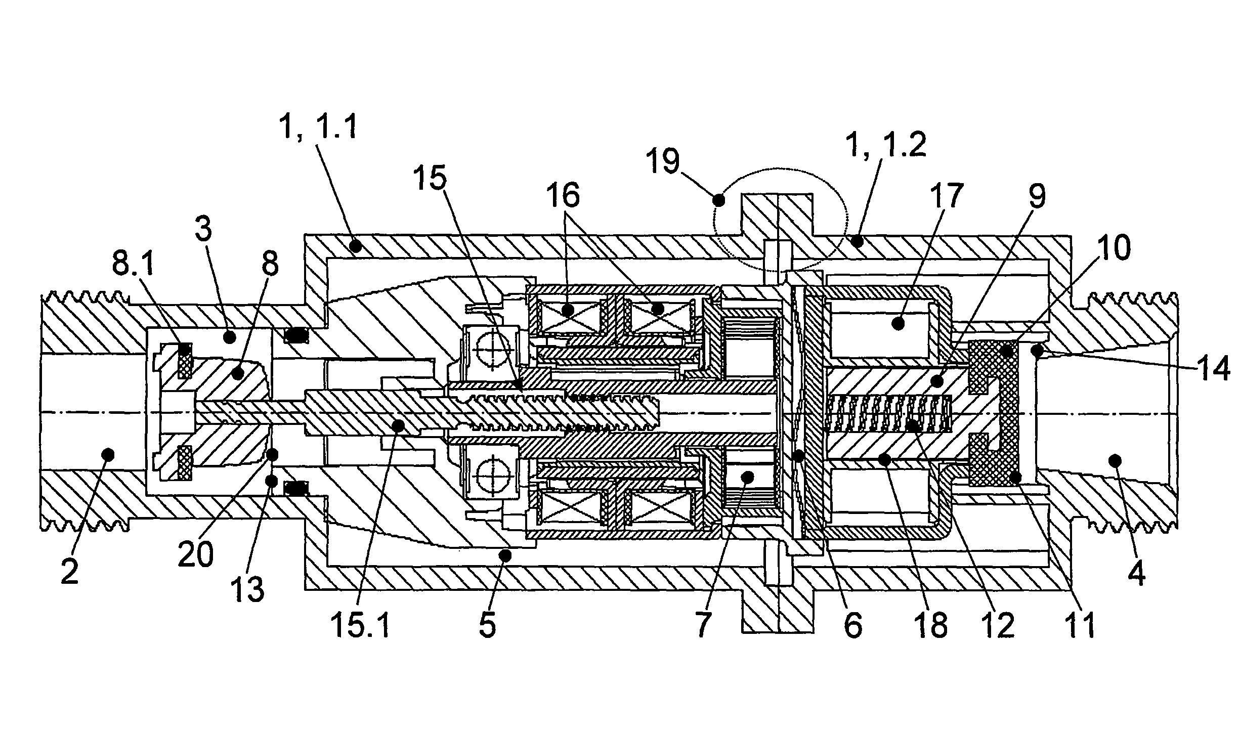
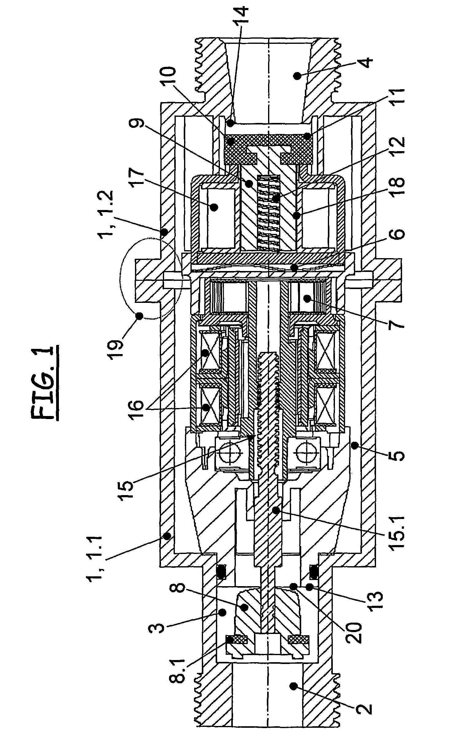
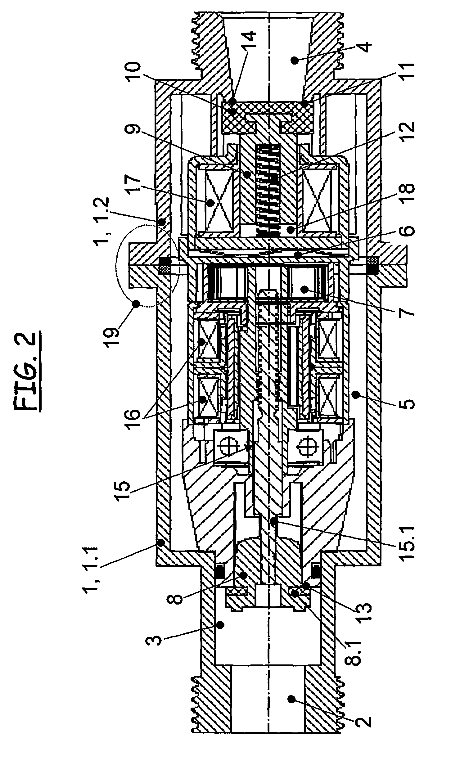
[0039]FIGS. 1 and 2 show the same gas control and safety valve of the invention with a spindle-nut system arranged inside the motor in a cross-sectional view in the closed position and in the open position, respectively. The gas control and safety valve consists of a two-part housing with a first housing part 1.1 and a second housing part 1.2. The outer surfaces of both housing parts 1.1 and 1.2 are screwed together in their coupling region and sealed. The inlet channel 2 with the inlet chamber 3 arranged downstream in the gas flow direction is disposed at the end of the first housing part 1.1. The outlet chamber is located at the end of the second housing part. The first closure element operating in the direction of the inlet channel 2 and the second closure element operating in the direction of the outlet channel represent a central component located inside the housing. The respective axes of the two closure elements are spaced from one another and extend sequentially in a straigh...


PUM


Abstract

The invention relates to an integrated gas regulating and safety valve for burners of a modulatable gas heating device. According to the invention, the gas regulating and safety valve comprises a housing (1) with two controllable closing elements, the axes of which are spaced apart from each other and extend one behind the other in series in the direction of gas flow between an inlet channel (2) and an outlet channel (4) of the housing. In the de-energized state, the two closing elements abruptly close the gas regulating and safety valve independently of each other, in each case by means of an associated spring element (7, 12). The first closing element, additionally serving for the modulation of the gas stream, has a drive spindle (15.1), which is formed as a spindle of a stepping motor (15), is surrounded by an excitation winding (16) and has placed on its end a restrictor component (8) and, at a distance from that, the first spring element (7). The second closing element, on the other hand, has a closure component (8) connected to an armature (9), wherein the armature (9) is arranged in a cylindrical cavity (18) and operates against the force of the second spring element (12) acting on the armature (9). This cavity (18) is surrounded by an excitation winding (17) of the armature (9) that is formed as part of an electromagnet.

Description

[0001]This is an application filed under 35 USC §371 of PCT / DE2007 / 001406 and claiming priority under DE 10 2006 041 872.7 filed on Aug. 31, 2006.BACKGROUND OF THE INVENTION[0002]The invention relates to an integrated gas control and safety valve for a burner of a modulatable gas heating device which is configured to adapt to a changeable thermal load and to abruptly turn off the gas flow, in particular for heating living areas and for gas heaters that supply hot water.[0003]Gas control and safety valves of this type typically include two electrically controllable actuator units, namely a rapidly closing valve and a modulation valve. The two independently operating actuator units are operated by electromagnets and are closed in the de-energized state by return springs. For modulating the gas flow, the modulation valve is additionally fine-adjusted by a proportional magnet or a stepper motor, so that two rapid closure functions and a modulating function can be realized with two actua...

Claims


Application Information

Patent Timeline
Patent Type & Authority Patents(United States)
IPC IPC(8): F16K31/06
CPCF16K31/04F16K31/0658F23N1/005F23K2900/05001F23N2035/14F23N2035/16F23N2035/18Y10T137/87917Y10T137/7764F23N2235/18F23N2235/16F23N2235/14
Inventor ROSCHKE, THOMASKOHLER, JORGGAMOT, MICHEL
Owner SAIA BURGESS DRESDEN
Learn More