Distorted aberration correction processing apparatus
a processing apparatus and aberration correction technology, applied in the field of distortion aberration correction processing apparatus, can solve the problems of reducing access rate, reducing performance, and deformation of captured images on the periphery, and preventing the lowering of the access rate of memory
- Summary
- Abstract
- Description
- Claims
- Application Information
AI Technical Summary
Benefits of technology
Problems solved by technology
Method used
Image
Examples
first embodiment
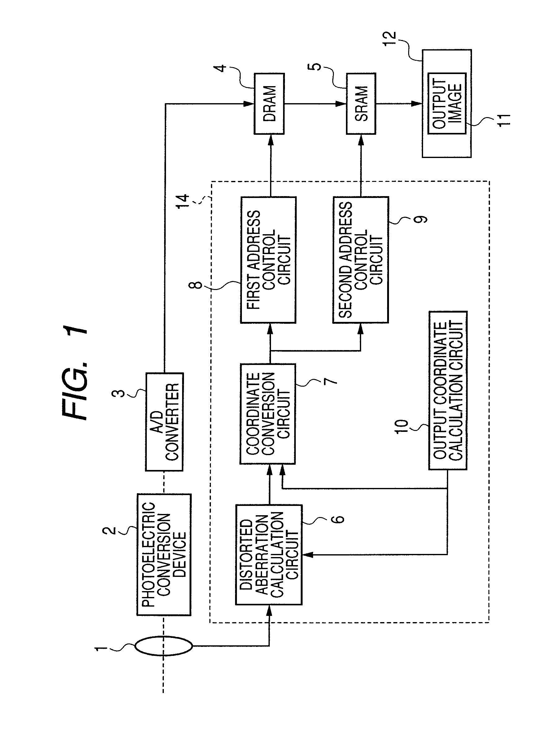
[0024]FIG. 1 is a block diagram illustrating a rough configuration of an image capture system according to a first exemplary embodiment of the present invention. The image capture system according to the present invention includes a lens system 1 and an image capture apparatus. The image capture apparatus includes: a photoelectric conversion device 2; an A / D converter 3; DRAM 4; SRAM 5; and a distorted aberration correction processing apparatus 14. The distorted aberration correction processing apparatus 14 includes: a distorted aberration calculation circuit 6; a coordinate conversion circuit 7; a first address control circuit 8; a second address conversion circuit 9; and an output coordinate calculation circuit 10.
[0025]The lens system 1 serves as an optical system. This lens system 1 includes at least one lens and converges light incident from the side of an object. The photoelectric conversion device 2 converts light which passed through the lens system 1 into an electrical sign...
second embodiment
[0054]FIG. 8 is a block diagram illustrating a rough configuration of an image capture system according to a second exemplary embodiment of the present invention. The coordinate transformation part and the part relative to readout of DRAM 4 are similar to the first embodiment, but including two banks of SRAM, i.e. a first SRAM 5a and a second SRAM 5b makes a difference from the first embodiment.
[0055]In the present embodiment, while the first SRAM 5a is read out and a first output division unit is output, a rectangular area in DRAM 4 corresponding to a second output division unit is read out and stored in the second SRAM 5b. While the second SRAM 5b is read out and the second output division unit is output, a rectangular area in DRAM 4 corresponding to a third output division unit is read out and stored in the first SRAM 5a. According to the second embodiment, compared to the configuration of the first embodiment, waiting time is shorter.
[0056]Also in the second embodiment, as shown...
third embodiment
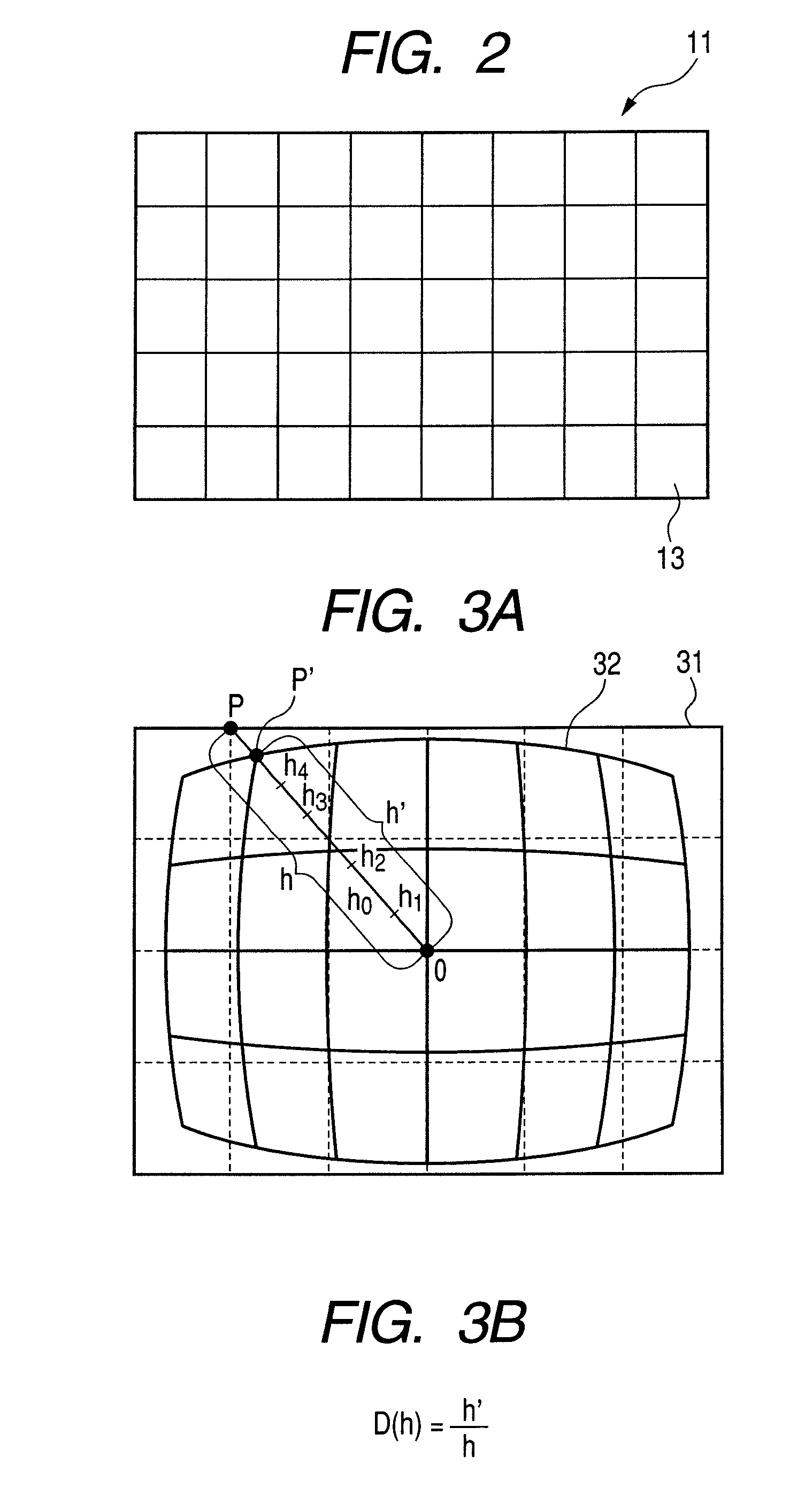
[0059]FIG. 10 is a block diagram illustrating a rough configuration of an image capture system according to a third exemplary embodiment of the present invention. The configuration except the lens system is similar to that of the second embodiment. A plurality of lenses constituting a lens system 1 includes a zoom lens 81, and a zoom encoder 82 is mounted. A distorted aberration calculation circuit 6 retains a distortion ratio as shown in FIG. 11 at a plurality of zoom positions. In FIG. 11, a distortion ratio D(h, x) is obtained from a height of image h and the zoom position x. Similarly to FIG. 4, at an intermediate zoom position or height of image, the distortion ratio can be obtained from interpolation based on the distorted aberration data at zoom positions in front of and behind the position which have the distorted aberration data.
PUM
 Abstract
Description
Claims
Application Information
 - R&D
- Intellectual Property
- Life Sciences
- Materials
- Tech Scout
- Unparalleled Data Quality
- Higher Quality Content
- 60% Fewer Hallucinations
Browse by: Latest US Patents, China's latest patents, Technical Efficacy Thesaurus, Application Domain, Technology Topic, Popular Technical Reports.
© 2025 PatSnap. All rights reserved.Legal|Privacy policy|Modern Slavery Act Transparency Statement|Sitemap|About US| Contact US: help@patsnap.com


