
Hardware overvoltage disconnecting circuit

a disconnecting circuit and overvoltage technology, applied in the direction of emergency protective arrangements for limiting excess voltage/current, electrical equipment, etc., can solve the problems of increased cost, decreased reliability, and delay in protection, so as to reduce the cost of the system, restrict the charging voltage, and mitigate the startup current

Active Publication Date: 2012-01-17
VERTIV CORP
View PDF7 Cites 7 Cited by
  • Summary
  • Abstract
  • Description
  • Claims
  • Application Information

AI Technical Summary

Benefits of technology

[0004]The object of the present invention is to provide a hardware overvoltage disconnecting circuit which can response timely and implement immediate protection when the power supply module are power-on, so that the power supply module is disconnected from the power network when the voltage of the power network increases to a predetermined value (or when both the voltages of the power network and the DC busbar reach the predetermined value), and the power supply module is connected to the power network when the voltage of the power network comes back to a certain value (or when both the voltages of the power network and the DC busbar come back to the certain value).
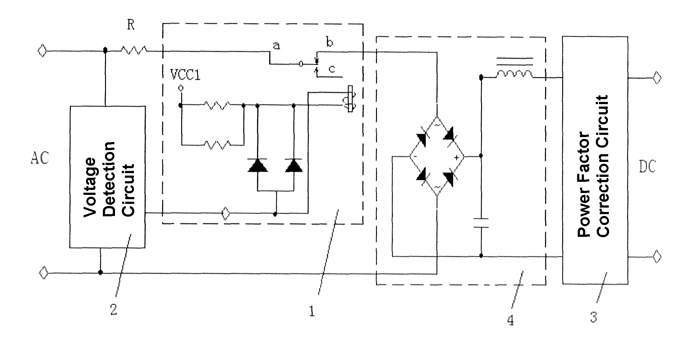
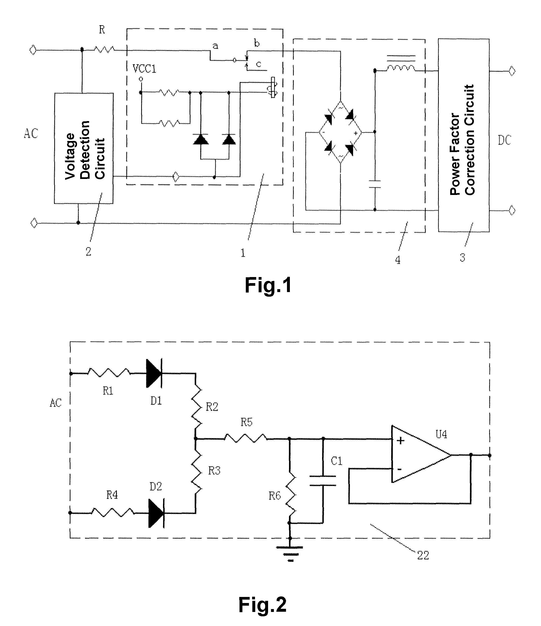
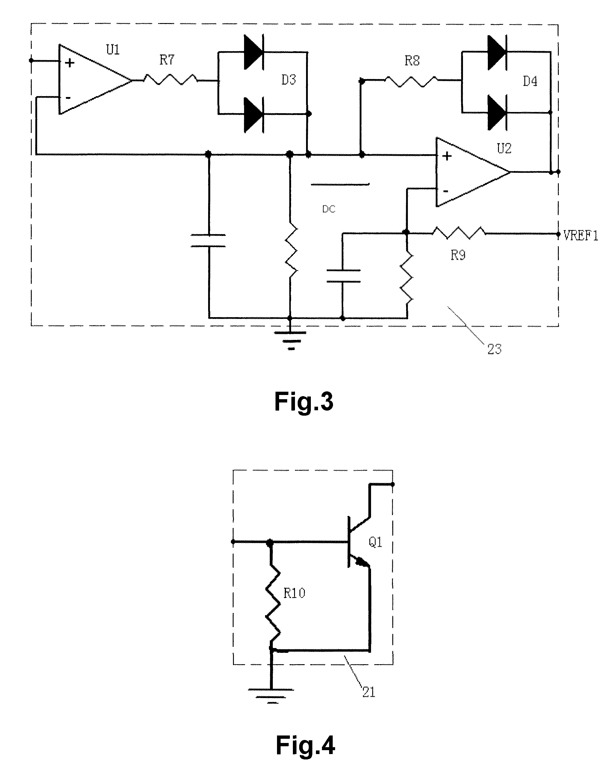
[0017]The hardware overvoltage disconnecting circuit of the present invention samples the voltage value from the AC input of the power supply module, and disconnects the power supply module (typically the rectifier module in the power supply module) from the power network before the voltage of the power network reaches its extreme value, such that the protection circuit is started up before the busbar voltage reaches its extreme value, and the relay can still work even if only the auxiliary power supply is working among all the components of the power supply module. The circuit of the present invention simultaneously detects the DC busbar voltage, which functions as one of the factors used to determine whether or not the relay is to be disconnected. Thus a false protection resulted from a transient overvoltage is avoided. Meanwhile the circuit of the present invention continuously monitors the voltage of the power network (or simultaneously monitoring the voltage of the DC busbar) after the power supply module is disconnected from the power network, and re-connects the power supply module to the power network when the voltage of the power network returns to a certain value, thus the disconnecting relay 1 works in a hiccup mode. The circuit of the present invention always keeps the auxiliary power supply of the module in a work state by the intermittent charging of the busbar capacity. A peak holding circuit is used in the voltage detection circuit 2, such that the power supply module still has accurate sample value after the power supply module is disconnected from the AC power network. Meanwhile, the series connection of the disconnecting relay 1 and the current limiting resistor mitigates the startup current and restricts the charging voltage, and also functions to protect the relay and downsize the relay, and thus the cost of the system is reduced.

Problems solved by technology

In this way, there exists a problem of the delayed protection.
Therefore, the power supply module may have a possibility of breaking down or may break down immediately.
However, this leads to increased costs and decreased reliability

Method used


Image

  • Hardware overvoltage disconnecting circuit
  • Hardware overvoltage disconnecting circuit
  • Hardware overvoltage disconnecting circuit

Examples


first embodiment

The First Embodiment

[0029]As shown in FIG. 1, a hardware overvoltage disconnecting circuit of the present invention comprises a disconnecting relay 1 and a voltage detection circuit 2. The voltage detection circuit 2 comprises an AC voltage detection section and a driving section 21, which are connected in series. The AC voltage detection section comprises a voltage sampling unit 22 and a peak-holding and logic-judging unit 23, which are connected in series.

[0030]Wherein, the disconnecting relay 1 is connected in series between the AC power network and a rectifier filter circuit 4 of the power supply module, and may be connected in series to any input loop of the rectifier filter circuit 4. A switch (dynamic switch) of the disconnecting relay 1 is connected with one terminal of the AC power network. A normally closed contact b of the disconnecting relay 1 is connected with the first input of the rectifier filter circuit 4, and a normally opened contact c of the disconnecting relay 1...

second embodiment

The Second Embodiment

[0036]As shown in FIG. 5, the hardware overvoltage disconnecting circuit of the present embodiment differs from that of the first embodiment in that the disconnecting relay 1 is connected in series between the rectifier filter circuit 4 and the power factor correction circuit 3 (PFC circuit), which has the same operational principle as that of the first embodiment.

third embodiment

The Third Embodiment

[0037]As shown in FIGS. 6 and 7, the hardware overvoltage disconnecting circuit of the present invention includes a disconnecting relay 1 and a voltage detection circuit 2. The voltage detection circuit 2 includes an AC voltage detection section, a busbar voltage detection section 24, and a driving section 21, which are connected in series. In this embodiment, the connection of the disconnecting relay 1 is the same as that of the first embodiment. The circuit construction and operational principle of the AC voltage detection section and the driving section 21 are similar to those in the first embodiment, that is, the voltage detection circuit 2 is the same as that of the first embodiment, comprising a voltage sampling unit 22, a peak-holding and logic-judging unit 23 which are connected in series; the circuit of the driving section 21 is the same as that of the first embodiment. What is different is that the input of the voltage sampling unit 22 and the input of ...


PUM


Abstract

The invention relates to a voltage detection control technology, especially relate to a hardware overvoltage disconnecting circuit wherein a DC power supply module is disconnected from a power network when the AC power network is in the state of overvoltage. The hardware overvoltage disconnecting circuit comprises a disconnecting relay and a voltage detection circuit. The disconnecting relay is connected in series between an AC power network and a power factor correction circuit of a power supply module. A first sampling terminal of the voltage detection circuit samples the voltage of the AC power network between the AC power network and the disconnecting relay, and an output of the voltage detection circuit is connected to a control terminal of the disconnecting relay. When the AC power network is in the state of overvoltage, the disconnecting relay is disconnected and the power supply module is disconnected from the AC power network. When the voltage of the AC power network is normal, the disconnecting relay is connected. The circuit of the present invention is started up before the busbar voltage reaches its extreme value, and the relay can still work even if only the auxiliary power supply is working among all the components of the power supply module. The auxiliary power supply of the module is still in the work state. The cost of the system is reduced.

Description

CROSS-REFERENCE TO RELATED APPLICATIONS[0001]This application is a U.S. National Stage Application of International application No. PCT / CN2007 / 000508. filed Apr. 13, 2007 which was published in English as WO 2007 / 118400 on Oct. 25, 2007. This application claims the benefit of Chinese Application No. 200610074786.7, filed Apr. 13, 2006. The disclosures of the above applications are incorporated herein by reference.FIELD OF THE INVENTION[0002]The present invention relates to a field of voltage detection and control, and particularly relates to a hardware overvoltage disconnecting circuit which disconnects the power supply module (rectifier module) from the power network when the AC power network is in the state of overvoltage.BACKGROUND OF THE INVENTION[0003]In the prior art, there is a blind area about overvoltage protection, that is, at the moment of power on, the module input overvoltage protection is performed by the protection circuit of the module in normal work state. In this w...

Claims


Application Information

Patent Timeline
Patent Type & Authority Patents(United States)
IPC IPC(8): H02H3/20H02H9/04
CPCH02H7/1252
Inventor ZHU, CHUNHUIHUANG, JINGJINGLIU, SHUDU
Owner VERTIV CORP
Learn More