
Apparatus for a junction point between two electrical high-voltage cables

a technology of electrical high-voltage cables and accessories, which is applied in the direction of electrical apparatus, electrically conductive connections, basic electric elements, etc., can solve the problems of high complexity and inability to connect cables such as these, and achieve the effect of avoiding the use of cables whose insulation

Inactive Publication Date: 2012-01-17
NEXANS
View PDF14 Cites 9 Cited by
  • Summary
  • Abstract
  • Description
  • Claims
  • Application Information

AI Technical Summary

Benefits of technology

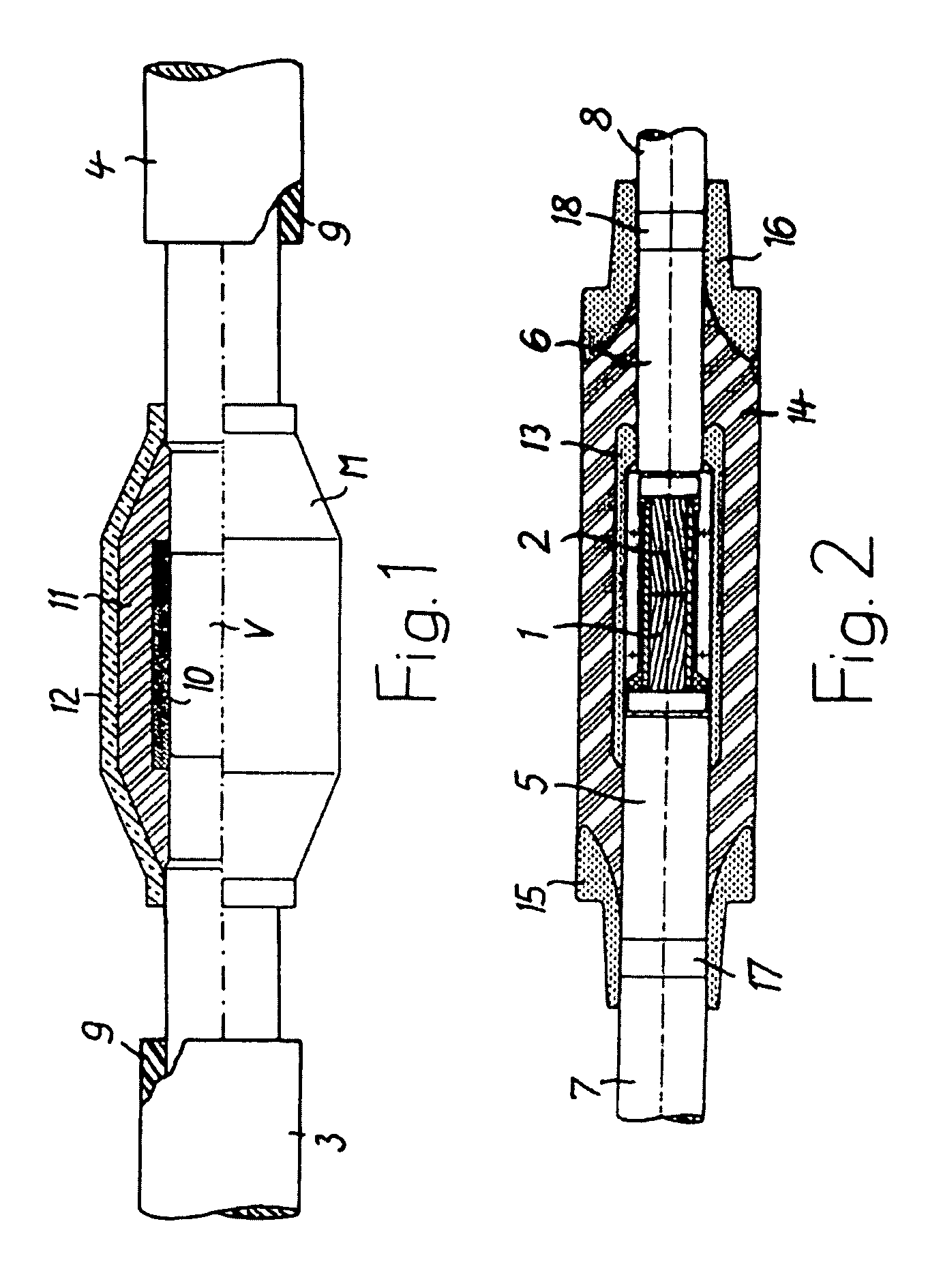
[0008]When using this sleeve body, the simple and advantageous connection technique, for example as is described in the initially cited EP 1 158 638 B1, can also be used for two high-voltage cables whose insulation has a considerably different diameter. The internal diameters of the two openings, which are provided at the ends of the sleeve body, of the through-hole are of such a size that they can on the one hand be pushed onto one of the cables, before the through-connection of the two conductors, without any risk of overstraining them. On the other hand, the sleeve body is pressed with a defined force against the outer conductive layers at both ends with the control funnels that are located there, despite the greatly different external diameters of the insulation on the two cables, to be precise with at least approximately the same force on both cables. This is of major importance for the functionality of the sleeve body because the defined sizes of the ends of the through-hole allow this to be done without damage, in particular in the event of temperature fluctuations, such as those which occur during operation of a cable run.

Problems solved by technology

It cannot be used to connect cables whose insulation has widely different external diameters.
The complexity for the connection of cables such as these is correspondingly high.

Method used


Image

  • Apparatus for a junction point between two electrical high-voltage cables
  • Apparatus for a junction point between two electrical high-voltage cables

Examples


Embodiment Construction

[0013]The conductors 1 and 2, which can be seen in FIG. 2, of two high-voltage cables 3 and 4—referred to in the following text as “cables 3 and 4”—are electrically conductively connected to one another at a junction point V. The conductors 1 and 2 may have a number of strands or may be solid. They may also be round or segmented. They may be composed of copper or aluminium. The conductors 1 and 2 are each surrounded by an inner conductive layer, which is also referred to as conductor smoothing. This conductive layer, which contains soot particles by way of example, is not shown in the drawing.

[0014]Extruded insulation 5 and 6 is respectively fitted over the inner conductive layer and is surrounded by a respective outer conductive layer 7 and 8. The outer conductive layers 7 and 8 may be formed in precisely the same way as the inner conductive layers. Further layers of the respective cables 3 and 4 can be arranged above the outer respective conductive layer 7 or 8, and these further ...


PUM


Abstract

Apparatus for a connecting point between high-voltage cables, each cable having a conductor, inner conductive layer, insulation, outer conductive layer, and a sheath over the outer conductive layer and in which the conductors, from which the surrounding layers have been removed, are conductively connected to one another. The arrangement has electrical screening elements and an integral elongated sleeve body, composed of elastic insulating material and a through-hole. The sleeve body has at its axial ends, which are intended for the cable to pass through, electrical control funnels which abut the outer conductive layers, from which the sheaths have been removed. The internal diameters of the through-hole in the sleeve body, at its axial ends, are for its use in a connecting point of cables, having an external diameter of their insulation which differs by at least 10 mm, different in a defined manner and adapted to the different external diameters.

Description

RELATED APPLICATION[0001]This application claims priority to European Patent Application No. 08290146.3, filed on Feb. 13, 2008, the entirety of which is incorporated by reference.BACKGROUND[0002]1. Field of the Invention[0003]The invention relates to an apparatus for a junction point between two electrical high-voltage cables.[0004]2. Description of Prior Art[0005]GB-A-1 339 502 describes a connecting apparatus for two screened electrical high-voltage cables in which the conductors of the two high-voltage cables are electrically conductively connected to one another by means of a metallic clamping connector. Flexible tube sections are fitted over the screens thereof and are joined together integrally from an electrically conductive and an electrically non-conductive polymer material. The entire junction point is surrounded by a sleeve body which is composed of two parts, each of which lies over one of the two high-voltage cables. The two parts of the sleeve body are plugged togethe...

Claims


Application Information

Patent Timeline
IPC IPC(8): H01R4/00
CPCH02G15/188H02G15/105
Inventor AUE, VOLKERBAESCH, MANFREDCARDINAELS, JOZEF
Owner NEXANS
Learn More