
Method for producing viscous hydrocarbon using steam and carbon dioxide

a hydrocarbon and viscous technology, applied in the direction of fluid removal, insulation, borehole/well accessories, etc., can solve the problems of increasing the api gravity, difficult and expensive hydrocarbon recovery, and lowering the viscosity of the hydrocarbon in situ, so as to increase the production and reduce the viscosity of the hydrocarbon

Active Publication Date: 2012-01-10
WORLD ENERGY SYST
View PDF85 Cites 30 Cited by
  • Summary
  • Abstract
  • Description
  • Claims
  • Application Information

AI Technical Summary

Benefits of technology

[0009]After the soak interval, the operator opens valves at the wellhead to cause the hydrocarbon to flow into the borehole and up the well. The viscous hydrocarbon, having undergone pyrolysis and / or hydrovisbreaking during this process, flows to the surface for further processing. Preferably, the flow occurs as a result of solution gas created in the fractured zone from the steam, carbon dioxide and residual hydrogen. A downhole pump could also be employed. The carbon dioxide increases production because it is more soluble in the heavy hydrocarbon than steam or hydrogen or a mixture thereof. This solubility reduces the viscosity of the hydrocarbon, and carbon dioxide adds more solution gas to drive the production. Preferably, the portions of the carbon dioxide and hydrogen and warm water returning to the surface are separated from the recovered hydrocarbon and recycled. In some reservoirs, the steam reacts with carbonate in the rock formation and releases carbon dioxide, although the amount released is only a small percentage of the desired amount of carbon dioxide entering the heavy-oil reservoir.

Problems solved by technology

These reservoirs contain a very viscous hydrocarbon, often called “tar”, “heavy oil”, or “ultraheavy oil”, which typically has viscosities in the range from 3,000 to 1,000,000 centipoise when measured at 100 degrees F. The high viscosity makes it difficult and expensive to recover the hydrocarbon.
The temperature of the superheated steam is sufficiently high to cause pyrolysis and / or hydrovisbreaking when hydrogen is present, which increases the API gravity and lowers the viscosity of the hydrocarbon in situ.

Method used


Image

  • Method for producing viscous hydrocarbon using steam and carbon dioxide
  • Method for producing viscous hydrocarbon using steam and carbon dioxide
  • Method for producing viscous hydrocarbon using steam and carbon dioxide

Examples


Embodiment Construction

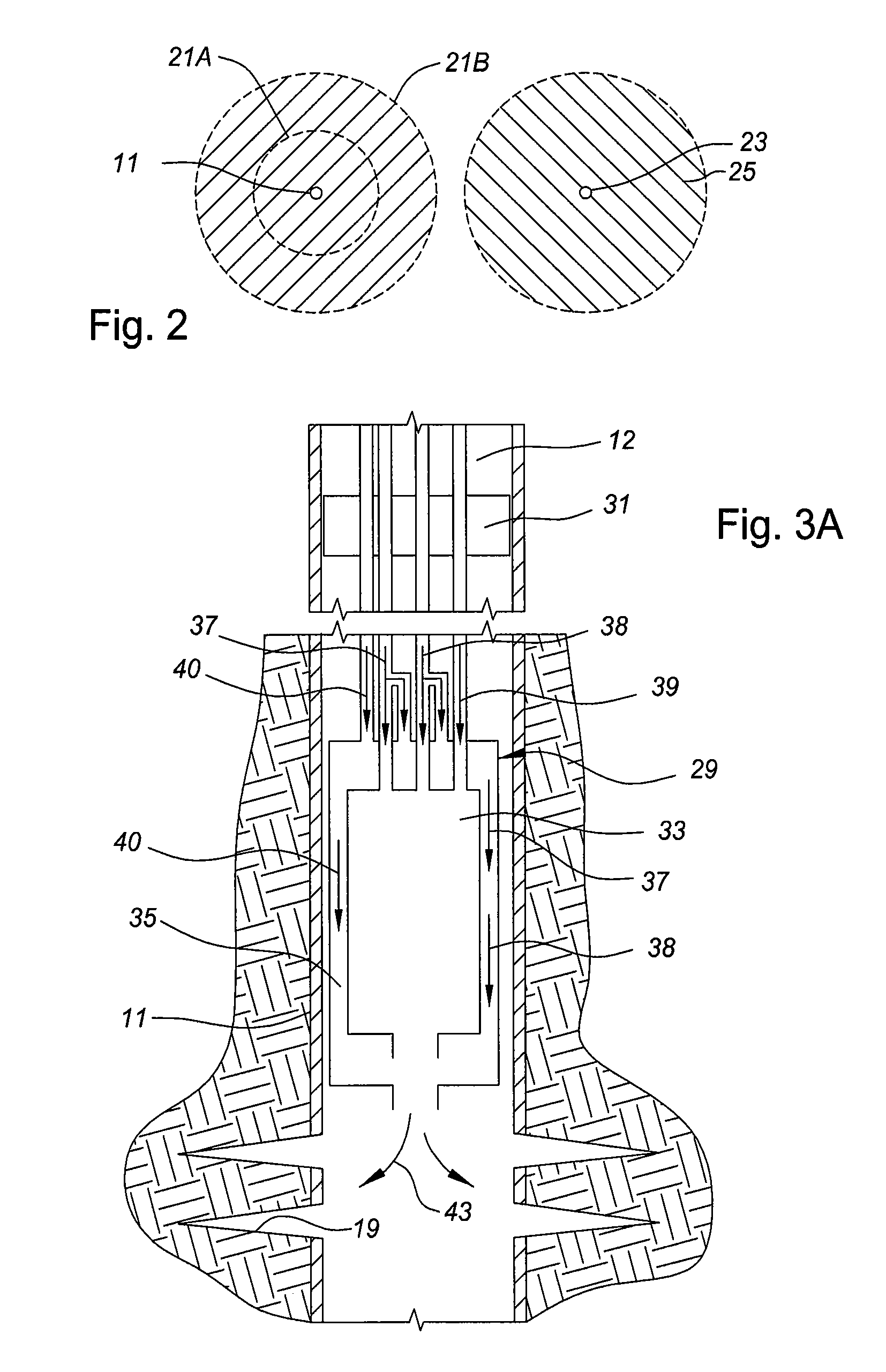
[0014]Referring to FIG. 1, well 11 extends substantially vertically through a number of earth formations, at least one of which includes a heavy oil or tar formation 15. An overburden earth formation 13 is located above the oil formation 15. Heavy-oil formation 15 is located over an underburden earth formation 17. The heavy-oil formation 15 is typically a tar sand containing a very viscous hydrocarbon, which may have a viscosity from 3,000 cp to 1,000,000 cp, for example. The overburden formation 13 may be various geologic formations, for example, a thick, dense limestone that seals and imparts a relatively-high, fracture pressure to the heavy-oil formation 15. The underburden formation 17 may also be a thick, dense limestone or some other type of earth formation.

[0015]As shown in FIG. 1, the well is cased, and the casing has perforations or slots 19 in at least part of the heavy-oil formation 15. Also, the well is preferably fractured to create a fractured zone 21. During fracturin...


PUM


Abstract

A downhole burner is used for producing heavy-oil formations. Hydrogen, oxygen, and steam are pumped by separate conduits to the burner, which burns at least part of the hydrogen and forces the combustion products out into the earth formation. The steam cools the burner and becomes superheated steam, which is injected along with the combustion products into the earth formation. Carbon dioxide is also pumped down the well and injected into the formation.

Description

FIELD OF THE INVENTION[0001]This invention relates in general to methods for producing highly viscous hydrocarbons, and in particular to pumping partially-saturated steam to a downhole burner to superheat the steam and injecting the steam and carbon dioxide into a horizontally or vertically fractured zone.BACKGROUND OF THE INVENTION[0002]There are extensive viscous hydrocarbon reservoirs throughout the world. These reservoirs contain a very viscous hydrocarbon, often called “tar”, “heavy oil”, or “ultraheavy oil”, which typically has viscosities in the range from 3,000 to 1,000,000 centipoise when measured at 100 degrees F. The high viscosity makes it difficult and expensive to recover the hydrocarbon. Strip mining is employed for shallow tar sands. For deeper reservoirs, heating the heavy oil in situ to lower the viscosity has been employed.[0003]In one technique, partially-saturated steam is injected into a well from a steam generator at the surface. The heavy oil can be produced ...

Claims


Application Information

Patent Timeline
Patent Type & Authority Patents(United States)
IPC IPC(8): E21B36/02E21B43/24
CPCE21B36/02E21B43/164E21B43/24
Inventor WARE, CHARLES H.KUHLMAN, MYRON I.
Owner WORLD ENERGY SYST
Learn More