
Satellite refuelling system and method

a refueling system and satellite technology, applied in the direction of liquid bottling, cosmonautic components, packaged goods, etc., can solve the problems of inability to robotically capture and service existing geostationary spacecraft, failure of primary propulsion system, etc., to prevent damage to the valve

Active Publication Date: 2011-12-13
MACDONALD DETTWILER & ASSOC INC
View PDF14 Cites 68 Cited by
  • Summary
  • Abstract
  • Description
  • Claims
  • Application Information

AI Technical Summary

Benefits of technology

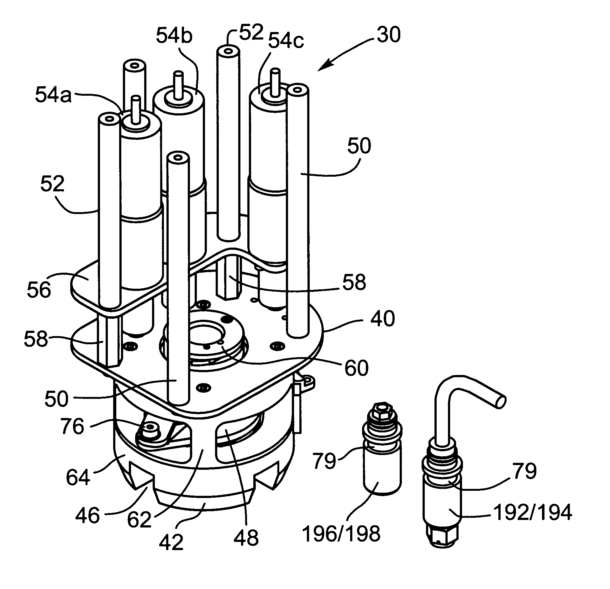
[0015]In another embodiment, the refueling system may be equipped with an artificial vision function which is used to register the worksite in the vicinity of the fill-drain valve, providing relative positions between the servicing arm / tool combination with the valves. The refueling system is then controlled in a supervised autonomous manner using an updated model of the worksite derived from the artificial vision function registration information. The system disclosed herein may also be used for fuelling for the first time satellites prior to launch, thereby eliminating or at least reducing the risk of a refueling technician being exposed to the toxic fuel in the event of a mishap.
[0026]a clamping mechanism mounted on said support frame to secure the valve tool to a reaction area on the fuel fill valve and oxidizer fill valve, said clamping mechanism being configured to localize torque generated by said valve tool for ensuring that any reaction torques from the socket drive mechanism are reacted locally to prevent damage to the valve; and

Problems solved by technology

Many geosynchronous orbit communication satellites currently in operation were designed with a finite amount of fuel and were not designed for the possibility of being refueled.
Some satellites suffer from primary propulsion system failures soon after they are launched.
The key technical difficulty is that these satellites were not designed for robotic servicing, and it is not generally accepted that such missions are technically possible.
Thus, accessing these fill and drain valves remotely presents several major challenges and would involve several operations, each of which is difficult to accomplish robotically including: cutting and removal of the protective thermal blankets, removal of several lockwires hand wrapped around the valves, unthreading and removing outer and inner valve caps, mating the fuel fill line to the valve nozzle, mechanically actuating the valve, and when refueling is complete, replacing the inner valve cap.
Robotic capture and servicing of existing geostationary spacecraft has never been demonstrated.
However a gap exists in the technologies required to service or re-fuel an un-prepared satellite in orbit.
To date there have been no technologies disclosed that can solve the problem of accessing the fuel system of an unprepared satellite for the purpose of replenishing station keeping fuel.
The technologies required to access the target spacecraft's fuel system for the purposes of refueling still have a very low technology readiness level, and are generally considered to be the main obstacle to a successful servicing mission.

Method used


Image

  • Satellite refuelling system and method
  • Satellite refuelling system and method
  • Satellite refuelling system and method

Examples


Embodiment Construction

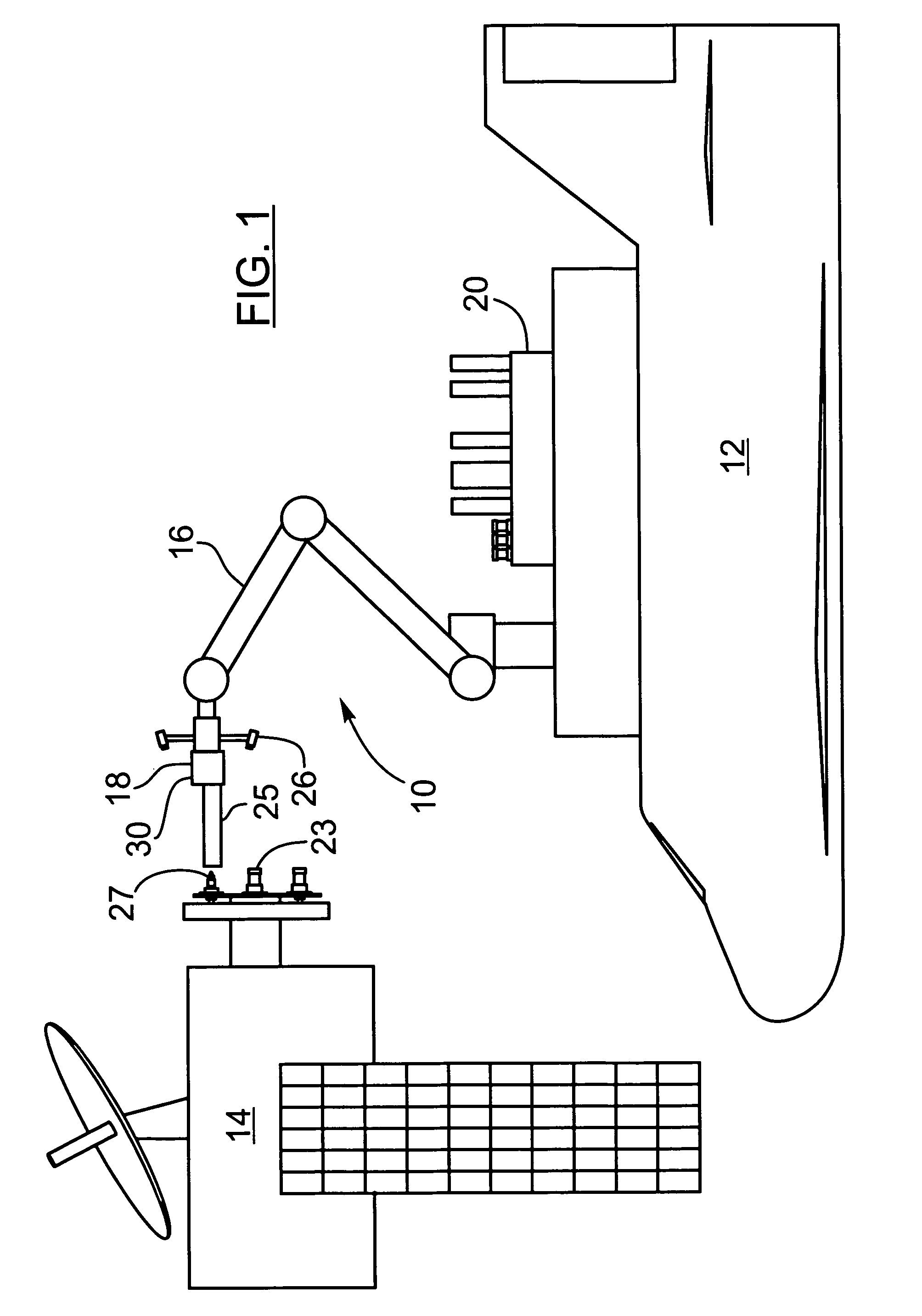
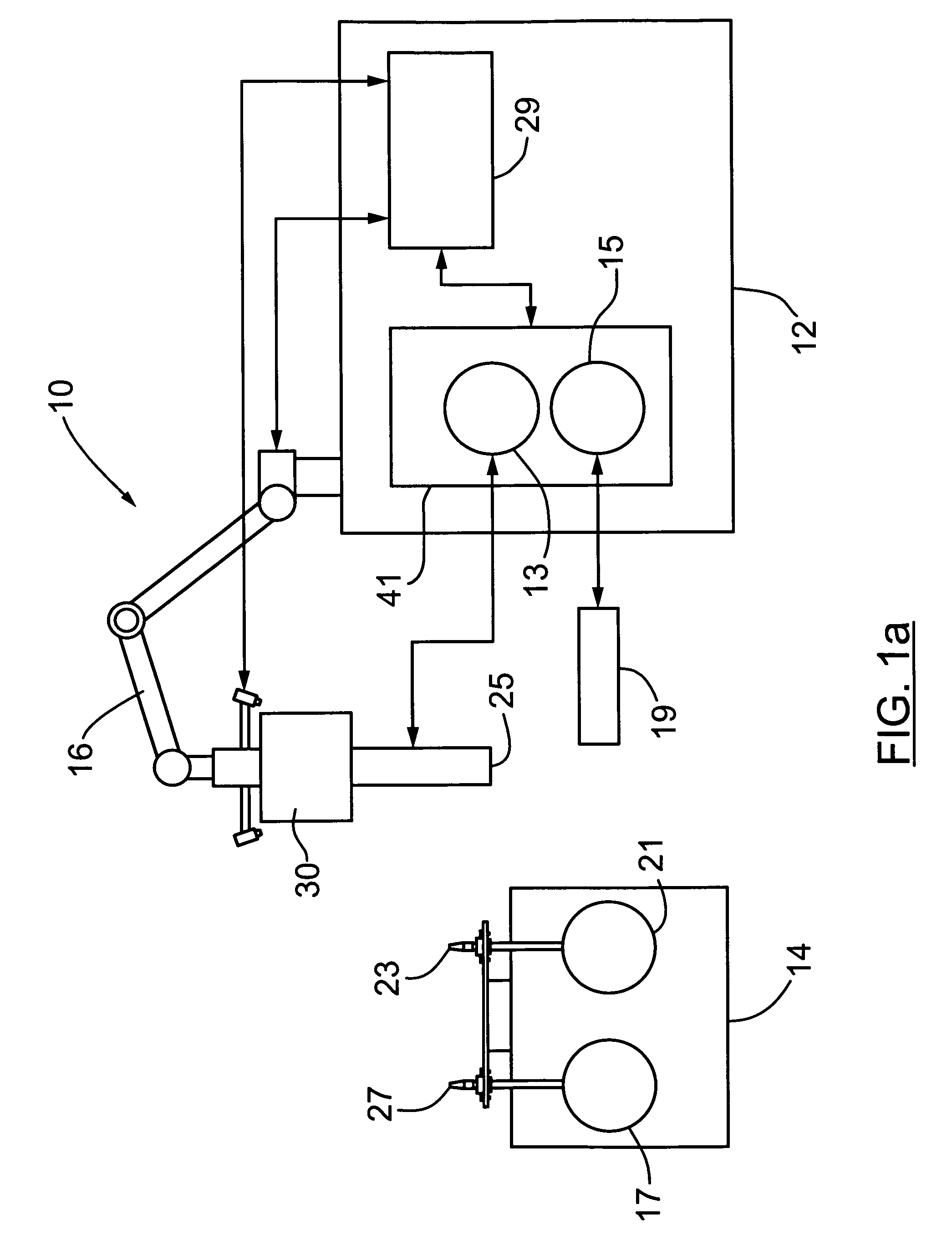
[0054]Generally speaking, the systems described herein are directed to a satellite refueling method and apparatus for refueling satellites. As required, embodiments of the present invention are disclosed herein. However, the disclosed embodiments are merely exemplary, and it should be understood that the invention may be embodied in many various and alternative forms. The Figures are not to scale and some features may be exaggerated or minimized to show details of particular elements while related elements may have been eliminated to prevent obscuring novel aspects. Therefore, specific structural and functional details disclosed herein are not to be interpreted as limiting but merely as a basis for the claims and as a representative basis for teaching one skilled in the art to variously employ the present invention. For purposes of teaching and not limitation, the illustrated embodiments are directed to a satellite refueling apparatus, system for and method for refueling satellites....


PUM

PropertyMeasurementUnit
relative displacementaaaaaaaaaa
torqueaaaaaaaaaa
dimensionsaaaaaaaaaa

Abstract

The present invention provides a method, system and apparatus for robotic refueling of satellites. The system may include a dedicated refueling satellite launched directly from either earth, or alternatively it could be launched from another larger mother spacecraft or space station in which the refueling satellite is ferried into space in the case of the larger space craft or it may be stored on the space station until needed from which it can be launched. The system includes a robotic arm, suitable tools which can be affixed to the end effector of the robotic arm required for accessing, opening and closing the fuel fill valve on the satellite being serviced, storage and retrieval stations on a tool caddy on which the tools and various fuel fill valve caps are stored. The system is under teleoperation by a remotely located operator, for example located on earth, in the mother station or in the space station. Cameras are included focussed on the robotic arm and end effector and images are transmitted to the operator to allow the operator to direct and control the refueling procedure. The system may also be configured to be operated autonomously under computer control.

Description

CROSS REFERENCE TO RELATED U.S. PATENT APPLICATION[0001]This patent application relates to U.S. provisional patent application No. 60 / 905,827 filed on Mar. 9, 2007 entitled ROBOTIC SATELLITE REFUELING METHOD AND SYSTEM, filed in English, which is incorporated herein in its entirety by reference.FIELD OF THE INVENTION[0002]The present invention relates to a satellite refueling system and method for refueling satellites.BACKGROUND OF THE INVENTION[0003]Many geosynchronous orbit communication satellites currently in operation were designed with a finite amount of fuel and were not designed for the possibility of being refueled. The design philosophy relied upon replacement of the satellites after they had exhausted the on-board fuel supply. In view of the expense of replacing satellites, it would be very advantageous to be able to refuel communication satellites which are either near their end of life, or have suffered an infant propulsion system failure, thereby extending their operat...

Claims


Application Information

Patent Timeline
Patent Type & Authority Patents(United States)
IPC IPC(8): B64G1/64
CPCB64G1/1078B64G1/14B64G1/402B64G4/00B64G5/00
Inventor GRYNIEWSKI, LAWRENCECRYMBLE, DERRYOWER, JOHN CAMERON
Owner MACDONALD DETTWILER & ASSOC INC
Learn More