Method of manufacturing a vibration damping bushing

a technology of vibration damping and manufacturing method, which is applied in the direction of shock absorbers, manufacturing tools, machine supports, etc., can solve the problems of insufficient proportion of the medial sleeve held by the positioning member (, body) and the tendency of the sleeve to be held in an unstable condition, so as to reduce the variability of characteristics and improve the accuracy of dimensional accuracy

Active Publication Date: 2011-12-06
SUMITOMO RIKO CO LTD
View PDF8 Cites 3 Cited by
  • Summary
  • Abstract
  • Description
  • Claims
  • Application Information

AI Technical Summary

Benefits of technology

[0011]It is therefore an object of the present invention to provide a vibration damping bushing that affords improved dimensional accuracy and reduced variability of characteristics, as well as a method for manufacturing it.
[0014]In the preferred mode of the present invention, the at least one positioning protrusion comprises three or more positioning protrusions separated from one another in the circumferential direction. More preferably, the positioning protrusions are disposed at three or more locations along the circumferential direction of the cavity defining face of the intermediate molds while being situated at equal intervals. In another preferred practice, the positioning protrusions will preferably be disposed at two or more locations lying in the axial direction. In this case, more preferably, one of the two locations is situated above an axially center portion of the cavity defining face. This can correct tilting of the medial sleeve in the axial direction. By providing these positioning protrusions, depressions corresponding to the positioning protrusions will be formed on the outside peripheral face of the rubber elastic body formed through vulcanization molding. Thus, in consideration of possible effects on the characteristics and durability of the rubber elastic body, it is preferable for the positioning protrusions to be situated at regions of thinnest wall thickness of the rubber elastic body which is positioned to the outer peripheral side of the medial sleeve, and the positioning protrusions will preferably be small enough that the required strength is assured.
[0015]In the present invention, the lower mold of the mold assembly is preferably furnished with a positioning portion for the purpose of positioning the lower end portion of the medial sleeve as it rests on the lower mold. This positioning portion can be constituted by ring-shaped groove extending in the circumferential direction, for example. This groove may be disposed continuously or in discontinuous segments in the circumferential direction. Where the groove is disposed in discontinuous segments, the loss of material in the rubber elastic body due to the positioning portion will be smaller. Where the lower mold is provided with a positioning portion for the medial sleeve in this way, the positioning protrusions provided to the intermediate molds will preferably be situated towards the upper side of the intermediate molds. This is so that tilting of the medial sleeve in the axial direction can be corrected to good advantage.
[0017]In the vibration damping bushing which pertains to the present invention, depressions corresponding to the positioning protrusions provided on the intermediate molds are formed on the outside peripheral face of the rubber elastic body during vulcanization molding of the rubber elastic body. Specifically, this vibration damping bushing affords improved dimensional accuracy and minimal variability of characteristics, due to the improved accuracy of positioning of the medial sleeve with respect to the mold assembly and the good coaxiality of the medial sleeve with respect of the main shaft member and the rubber elastic body.
[0019]According to the method of manufacturing a vibration damping bushing which pertains to the present invention, the main shaft member and the medial sleeve are positioned coaxially and resting in a vertical attitude on the lower mold, the intermediate molds are then moved in the centripetal direction, and vulcanization molding of the rubber elastic body is carried out with the outside peripheral face of the medial sleeve positioned by positioning protrusions disposed at three or more locations along the circumferential direction of the cavity wall of the intermediate molds, thus affording improving dimensional accuracy and reducing variability of characteristics.

Problems solved by technology

At this time, while the main shaft member can be held in stable condition by the positioning member, for structural reasons portion of the medial sleeve held by the positioning member (i.e. the portion projecting from the axial end face of the rubber elastic body) is insufficient.
Moreover, since there is dimensional variation (tolerance) of the medial sleeve, it is necessary to leave a gap (gutter) in the diametrical direction between the medial sleeve and the positioning member, so that the sleeve tends to be held in an unstable condition.
If the medial sleeve should shift out of position in this way, when the intermediate molds and the upper mold are set, the mold assembly or medial sleeve may become broken or deformed.
Also, if vulcanization molding is carried out with the medial sleeve shifted out of position, dimensional accuracy of the product will be poor so that characteristics vary appreciably, or defective products may occur.
However, since it is necessary to avoid interference with other components situated in proximity to the vibration damping bushing, there is a limit as to how much the length of the medial sleeve can be extended.

Method used


Image

  • Method of manufacturing a vibration damping bushing
  • Method of manufacturing a vibration damping bushing
  • Method of manufacturing a vibration damping bushing

Examples


Embodiment Construction

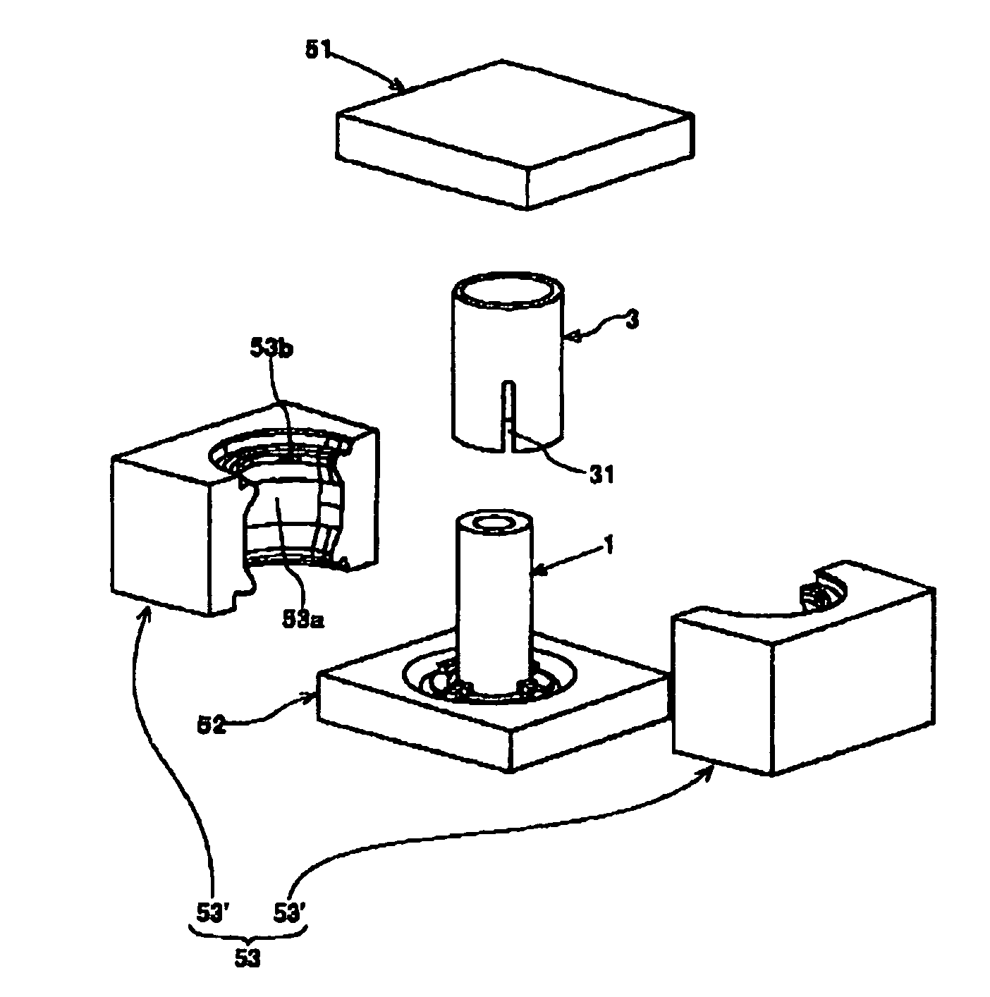
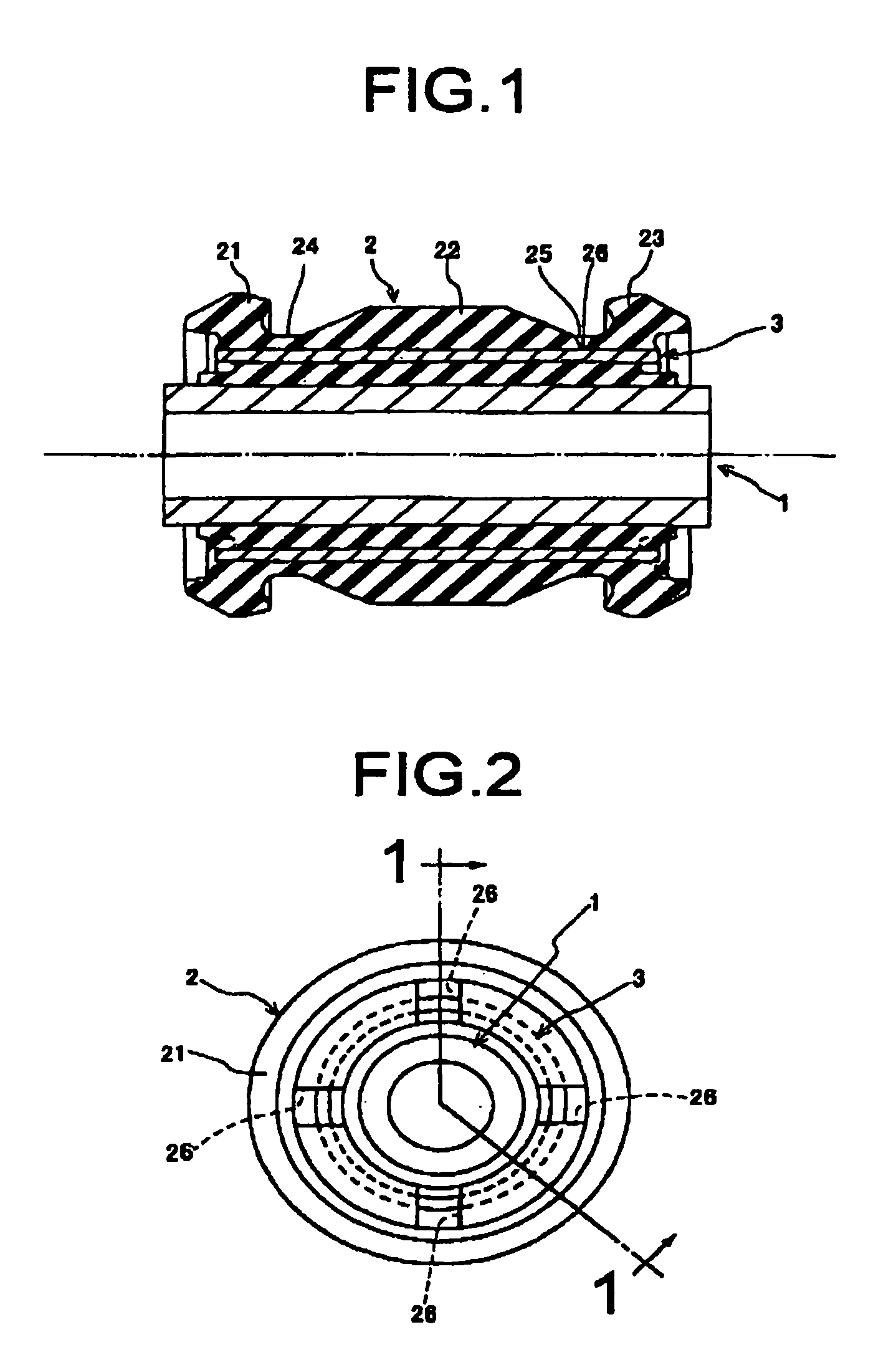
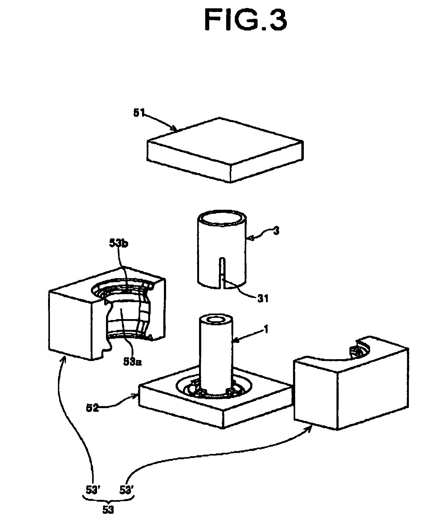
[0029]FIGS. 1 and 2 depict a vibration damping bushing manufactured according to a preferred embodiment of the present invention. The vibration damping bushing includes; a main shaft member 1 of thick-walled tubular shape; a rubber elastic body 2 of tubular shape affixed to the outside peripheral face of the main shaft member 1; and a medial sleeve 3 of tubular shape embedded in the medial region of the rubber elastic body 2 in the direction of its thickness and coaxial with the main shaft member 1 and the rubber elastic body 2. The rubber elastic body 2 has a central thick walled portion 22 and a pair of thick large-diameter portions 21, 23 that bulge diametrical outward situated at three locations in its axial center section and at either end, forming a pair of thin small-diameter portions 24, 25 recessed diametrically inward between the central thick walled portion 22 and the neighboring large-diameter portions 21, 23. In one of the small-diameter portions 25, there are formed fo...


PUM

PropertyMeasurementUnit
Poisson's ratioaaaaaaaaaa
thicknessaaaaaaaaaa
elasticaaaaaaaaaa

Abstract

A method of manufacturing a vibration damping bushing wherein after setting a main shaft member on a lower mold, an medial sleeve is set to be disposed about the main shaft member, and a plurality of sections are moved forward in a centripetal direction to form an intermediate mold together, and then an upper mold is superposed onto the intermediate mold to form a mold cavity therein. At least one positioning protrusion is formed on a cavity defining face, being discontinuous in a circumferential direction, while being located at either semi-circumference of the cavity defining face with any diametric line interposed therebetween. The medial sleeve is set in position in an axis-perpendicular direction within the mold cavity by holding the positioning protrusions in contact against an outer peripheral face of the medial sleeve. A vibration damping bushing manufactured by this method is also disclosed.

Description

INCORPORATED BY REFERENCE[0001]The disclosure of Japanese Patent Application No. 2007-079743 filed on Mar. 26, 2007 including the specification, drawings and abstract is incorporated herein by reference in its entirety.BACKGROUND OF THE INVENTION[0002]1. Field of the Invention[0003]The present invention relates to a vibration damping bushing adapted to provide vibration damping linkage to two components for which vibration transmission is to be prevented in an automobile, or alternatively adapted to provide vibration damping mounting of one of the two components on the other in a vibration damping fashion. The present invention also relates to a method of producing the same.[0004]2. Description of the Related Art[0005]Conventionally, suspensions for automobiles and the like have commonly employed vibration damping bushings composed of a main shaft member, a rubber elastic body of tubular shape affixed to the outside peripheral face of the main shaft member, and a medial sleeve of tu...

Claims


Application Information

Patent Timeline
Patent Type & Authority Patents(United States)
IPC IPC(8): B29C45/14
CPCF16F1/3842Y10T29/4998
Inventor IMAEDA, KENICHIRO
Owner SUMITOMO RIKO CO LTD
Why Eureka
Try Eureka