
Fuel cell system and its operation stop method

a fuel cell and operation stop technology, applied in the field of fuel cell systems, can solve the problems of wasting refrigerant control time, and achieve the effect of suppressing waste in the refrigerant control during the system stop

Active Publication Date: 2011-11-29
TOYOTA JIDOSHA KK
View PDF11 Cites 0 Cited by
  • Summary
  • Abstract
  • Description
  • Claims
  • Application Information

AI Technical Summary

Benefits of technology

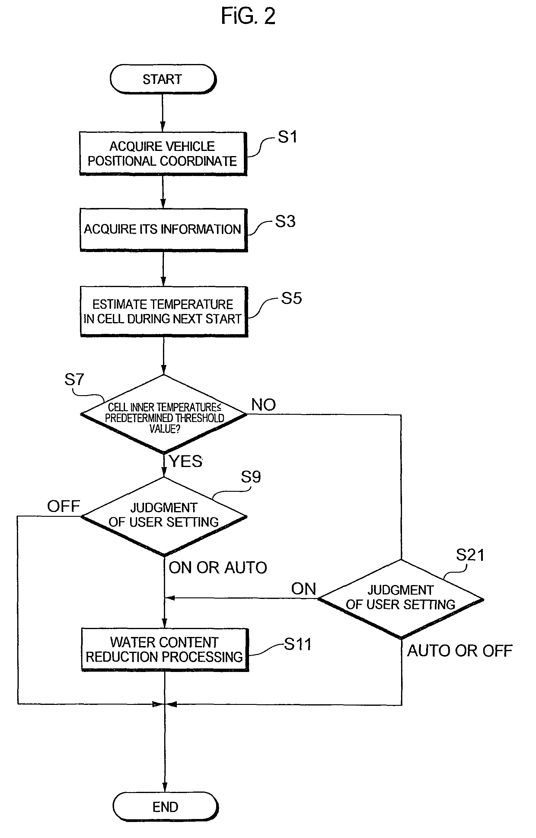
The present invention relates to a fuel cell system and a method for stopping and resuming the operation of the system. The invention takes into account the temperature of the fuel cell during the next system start or a temperature that has a correlation with the fuel cell temperature to control the refrigerant supply during system stop. This helps to prevent unnecessary refrigerant control and promotes power generation in the fuel cell during system stop. The invention also includes an abnormality judgment section to monitor the refrigerant system and alert of any abnormality. Overall, the invention reduces waste in refrigerant control and improves the efficiency of the fuel cell system.

Problems solved by technology

However, in the technologies disclosed in the above publications, the above refrigerant control is performed without considering any situation for the next system start, and hence there is a possibility that useless refrigerant control is performed.

Method used


Image

  • Fuel cell system and its operation stop method
  • Fuel cell system and its operation stop method
  • Fuel cell system and its operation stop method

Examples


Embodiment Construction

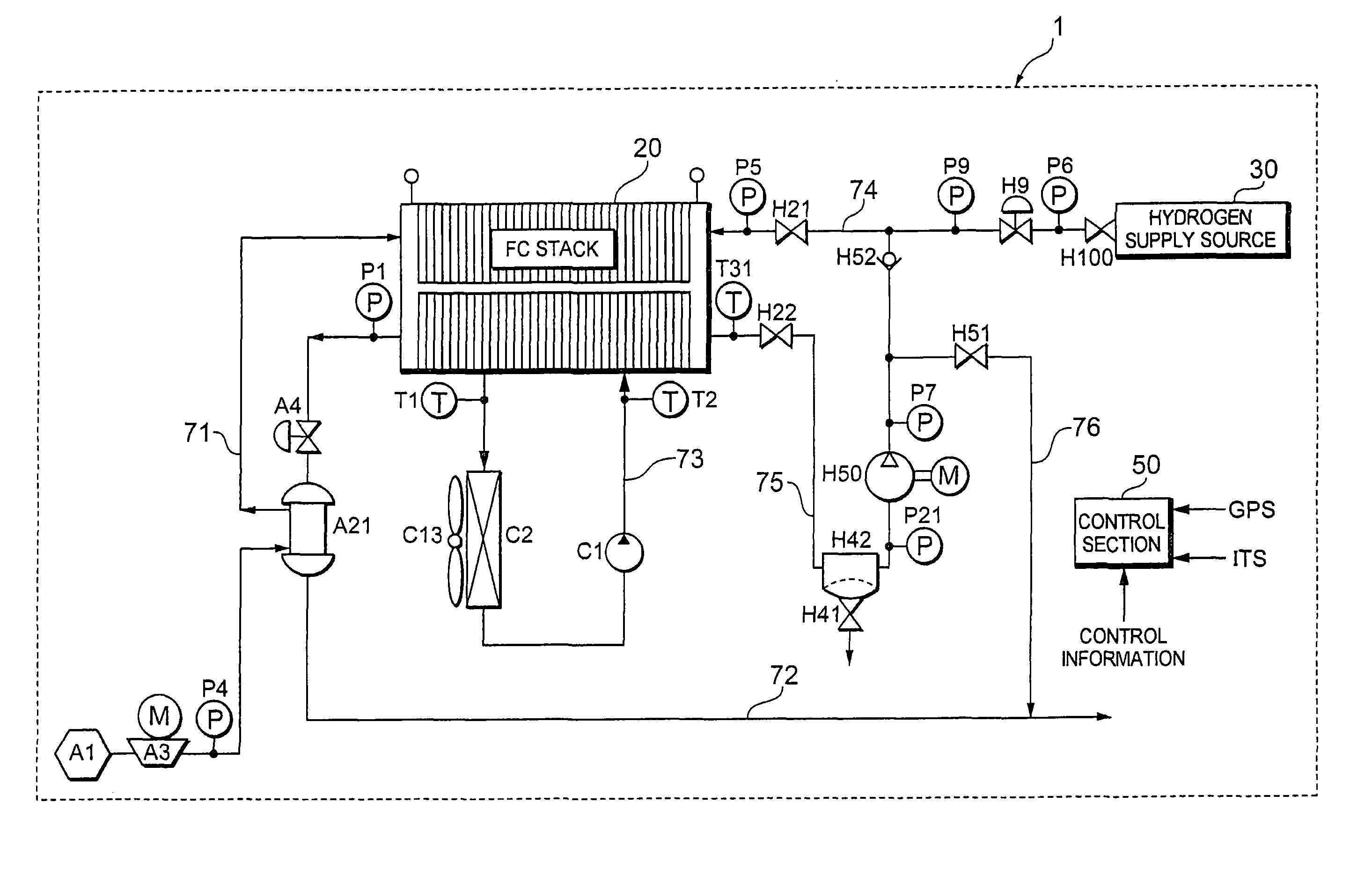
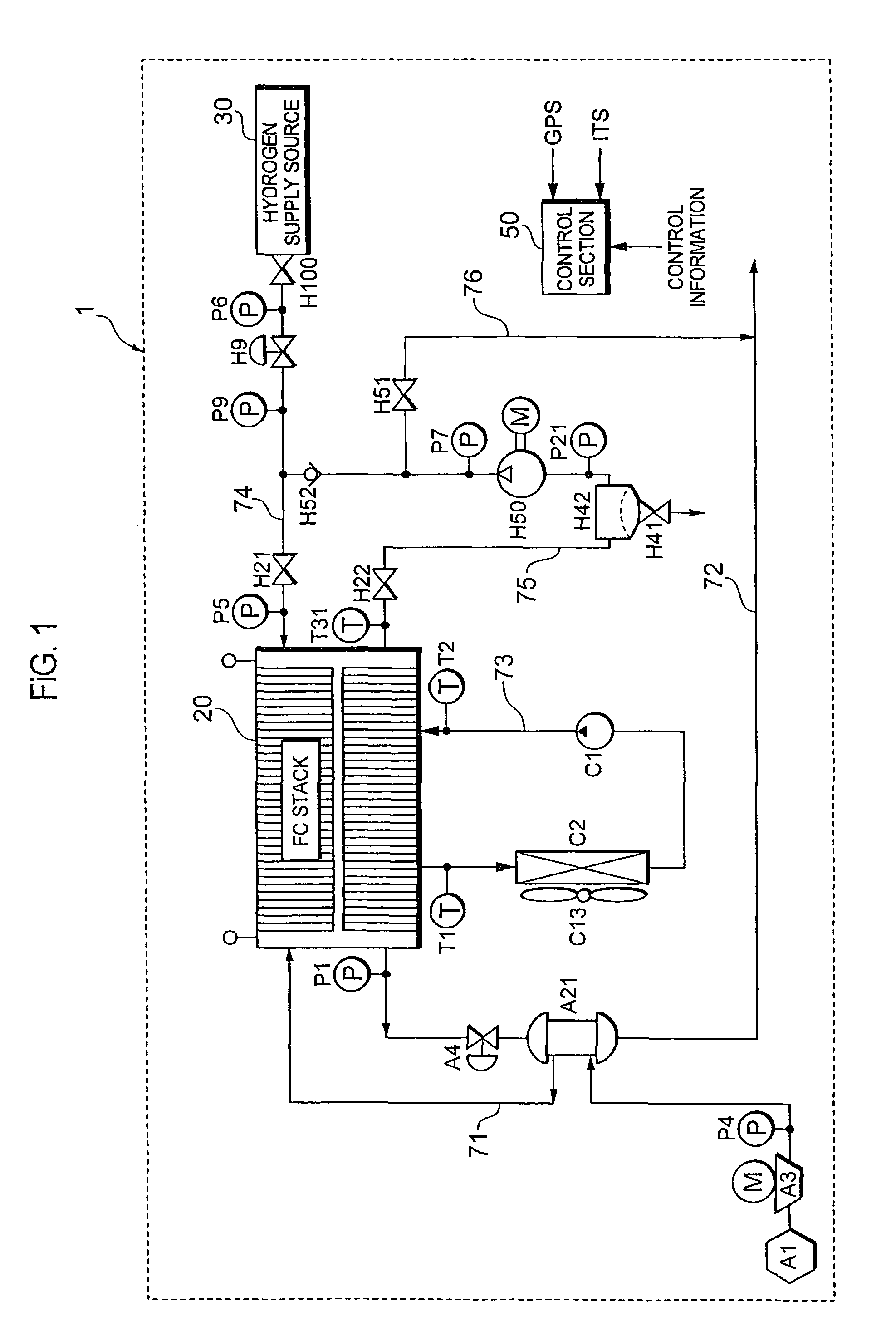
[0021]Next, one embodiment of a fuel cell system according to the present invention will be described. A case where this fuel cell system is applied to a vehicle-mounted power generation system of a fuel cell vehicle will hereinafter be described, but the present invention is not limited to such an application example. The present invention is applicable to any mobile body such as a ship, an airplane or a train or a walking robot, and is additionally applicable to a stationary power generation system in which a fuel cell is used as a power generation equipment for a construction (a housing, a building or the like).

[0022]As shown in FIG. 1, air (outside air) as an oxidizing gas (a reactive gas) is supplied to an air supply port of a fuel cell 20 via an air supply path 71. The air supply path 71 is provided with an air filter A1 which removes fine particles from air, a compressor A3 which pressurizes the air, a pressure sensor P4 which detects a supply air pressure, and a humidifier A...


PUM

PropertyMeasurementUnit
temperatureaaaaaaaaaa
poweraaaaaaaaaa
temperatureaaaaaaaaaa

Abstract

A fuel cell system includes a fuel cell which has a catalyst layer therein and which receives supply of a reactive gas to generate power, and a refrigerant system which supplies a refrigerant to the fuel cell to control its temperature. A method for stopping an operation of the system is also provided. When operated in a low-temperature environment, the system cannot be restarted due to freezing in the fuel cell. When the temperature of the fuel cell during the next system start is a predetermined temperature or less, the supply of the refrigerant is stopped during the system stop, and the supply of the refrigerant is resumed after elapse of a predetermined time.

Description

[0001]This is a 371 national phase application of PCT / JP2006 / 324311 filed 29 Nov. 2006, which claims priority of Japanese Patent Application No. 2005-358845 filed 13 Dec. 2005, the contents of which are incorporated herein by reference.TECHNICAL FIELD[0002]The present invention relates to a fuel cell system provided with a fuel cell which has a catalyst layer therein and which receives supply of a reactive gas to generate a power, and a method for stopping an operation of the system.BACKGROUND ART[0003]In recent years, a fuel cell system has received attention in which a fuel cell to generate a power by an electrochemical reaction of a fuel gas with an oxidizing gas (these gases will hereinafter be referred to as a reactive gas) is used as an energy source. For example, when a solid polymer type fuel cell is disposed in a low-temperature environment at 0° C. or less, proceeding of the electrochemical reaction is disturbed owing to freezing in the fuel cell, especially freezing of a ...

Claims


Application Information

Patent Timeline
Patent Type & Authority Patents(United States)
IPC IPC(8): H01M8/04
CPCH01M8/04029Y02E60/50H01M8/04
Inventor YOSHIDA, NAOHIRO
Owner TOYOTA JIDOSHA KK
Learn More