
Terminal structure of microspeaker

A micro-speaker and terminal structure technology, which is applied in the direction of sensors, electrical components, circuit lead arrangement/elimination, etc., can solve the problem of waste of terminal pads 70, and achieve the effect of preventing waste and facilitating assembly

Inactive Publication Date: 2015-07-01
EM TECHNOLOGY CO LTD
View PDF5 Cites 1 Cited by
  • Summary
  • Abstract
  • Description
  • Claims
  • Application Information

AI Technical Summary

Problems solved by technology

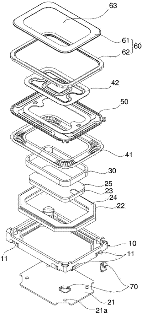
[0004] Considering that the conventional terminal pad 70 is coupled to the frame 10 during the molding process of the frame 10, if the frame 10 has a molding defect, if the terminal pad 70 embedded during the molding of the frame 10 has a defect, or if the terminal pad If the embedding position of the sheet 70 is not suitable during the molding of the frame 10, both the frame 10 and the terminal spacer 70 are disadvantageously wasted

Method used


Image

  • Terminal structure of microspeaker
  • Terminal structure of microspeaker
  • Terminal structure of microspeaker

Examples


Embodiment Construction

[0025] Hereinafter, the present invention will be described in more detail with reference to the accompanying drawings.

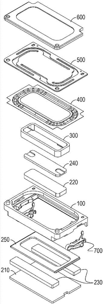
[0026] image 3 is an exploded perspective view showing a microspeaker having a terminal structure according to an embodiment of the present invention. In the microspeaker having the terminal structure according to one embodiment of the present invention, a magnetic circuit is provided in the frame 100, and a vibration unit is provided on the frame 100, which vibrates due to mutual electromagnetic force with the magnetic circuit and produce sound. A protector 600 positioned on the vibration unit is coupled to the frame 100 to protect the magnetic circuit and the vibration unit. In addition, a terminal 700 is coupled to the frame 100, the terminal 700 being in contact with an external power source to transmit an electric signal to the micro speaker.

[0027] set in image 3 In the illustrated magnetic circuit in the microspeaker, three magnets 220 and 23...


PUM


Abstract

The present invention relates to a terminal structure of the micro-speaker. More specifically, relates to a terminal structure of the micro-speaker. The terminal is connected to the frame structure and is in contact with the external power supply to deliver an electrical signal to a vibration unit in a frame.

Description

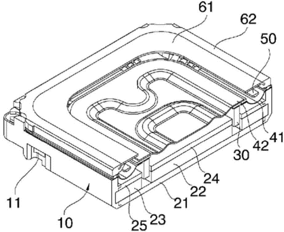
technical field [0001] The invention relates to a terminal structure of a micro speaker. More particularly, the present invention relates to a terminal structure of a microspeaker coupled to a frame and in contact with an external power source to transmit an electric signal to a vibration unit in the frame. Background technique [0002] figure 1 is an exploded perspective view showing a conventional microspeaker, and figure 2 is a cross-sectional view of a conventional microspeaker. In a conventional microspeaker, the yoke 21, the inner ring magnet 22, the outer ring magnet 23, the inner ring top plate 24 and the outer ring top plate 25 are arranged in the frame 10, and the voice coil 30 is arranged on the inner ring magnet 22 and the outer ring magnet 23. and vibrate vertically when power is applied to the voice coil 30 . The voice coil 30 is installed on the bottom surface of the hanger 50 , and the side diaphragm 41 and the center diaphragm 42 are disposed on the top...

Claims


Application Information

Patent Timeline
Patent Type & Authority Applications(China)
IPC IPC(8): H04R9/06H04R9/02
CPCH04R1/06H04R9/02
Inventor 郑仁镐金知炫
Owner EM TECHNOLOGY CO LTD
Learn More