Diesel-electric drive system

a technology of diesel-electric drive and drive controller, which is applied in the direction of electric generator control, electric devices, machines/engines, etc., can solve the problems of inability to use the brake controller in traction mode, the unused diode or igbt rectifier of the braking controller, etc., and achieve the effect of installing power or the chip area

Active Publication Date: 2011-11-22
SIEMENS AG
View PDF15 Cites 7 Cited by
  • Summary
  • Abstract
  • Description
  • Claims
  • Application Information

AI Technical Summary

Benefits of technology

[0011]Since a second generator-side self-commutated pulse-controlled converter is provided, the power of the generator-side self-commutated pulse-controlled converter of a diesel-electric drive system of the type in question is split between these two generator-side self-commutated pulse-controlled converters. This assumes that the generator now has two polyphase winding systems in the stator, instead of one winding system. This results in a further degree of freedom, which can be used for connection of the braking resistors. According to the invention, a braking resistor connects at least one input phase of one generator-side self-commutated pulse-controlled converter to a corresponding input phase of the second generator-side self-commutated pulse-controlled converter of the voltage intermediate-circuit converter.

Problems solved by technology

This has the disadvantage that a further converter bridge arm must be used for the braking controller, and the additional rail system for this braking controller must be provided with the intermediate-circuit rail system.
This procedure has the disadvantage that, in the braking mode, the rectifier (diode or IGBT rectifier) remains unused, while the braking controller cannot be used in the traction mode.
The problem is now to find a solution and a circuit in which the power semiconductors can be used both in the traction mode and in the braking mode without having to reconfigure the topology by means of circuit breakers in this case.

Method used


Image

  • Diesel-electric drive system
  • Diesel-electric drive system
  • Diesel-electric drive system

Examples


Embodiment Construction

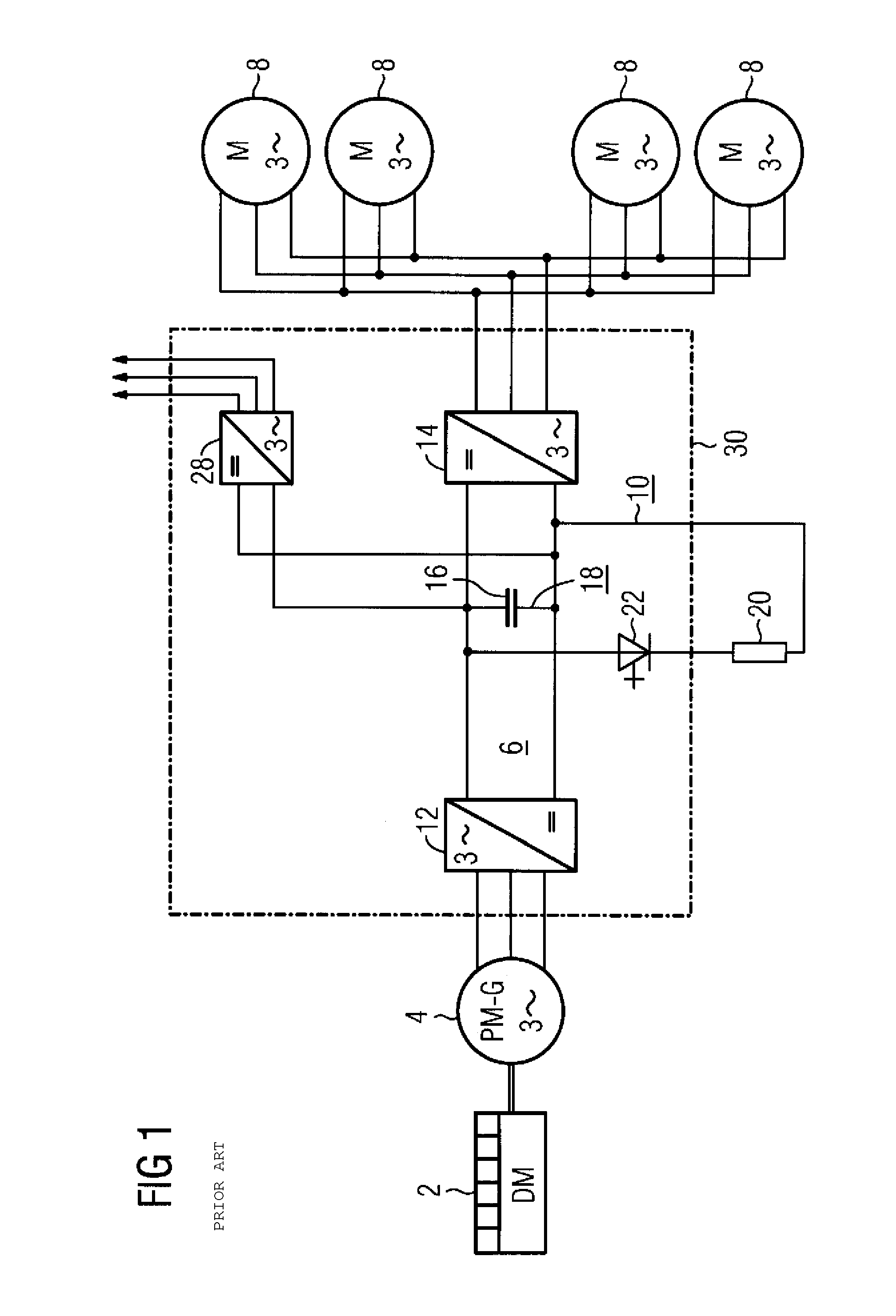
[0025]In FIG. 1, which illustrates an equivalent circuit of a diesel-electric drive system of this generic type, 2 denotes a diesel engine, 4 a generator, in particular a permanent-magnet synchronous generator, 6 a voltage intermediate-circuit converter, 8 a plurality of rotating-field machines, in particular three-phase asynchronous motors, and 10 denotes a braking chopper. The voltage intermediate-circuit converter has a generator-side and a load-side self-commutated pulse-controlled converter, 12 and 14, respectively, which are electrically conductively connected to one another on the DC voltage side by means of an intermediate circuit 18 which has an intermediate-circuit capacitor bank 16. The braking chopper 10 is connected electrically in parallel with this intermediate circuit 18 and has a braking resistor 20 and a braking controller 22, for example a thyristor which can be turned off, which are electrically connected in series. In addition, the illustration shows an auxiliar...


PUM


Abstract

A diesel-electric drive system having a generator mechanically connected to a diesel motor on the rotor side and linked to a voltage source (intermediate) inverter on the stator side. The voltage source inverter is connected to a self-commuting pulse power converter on the generator and on the load side as well as to a brake resistor. The generator has two multiple-phase coil systems which are each electroconductively linked to a self-commuting pulse power converter on the generator side, wherein the second self-commuting pulse power converter on the generator side is switched electrically parallel to the voltage source (intermediate) circuit of the voltage source (intermediate) inverter on the generator side. At least one input phase of the first self-commuting pulse power converter on the generator side is electroconductively linked via a brake resistor to a input phase of the second self-commuting pulse power converter on the generator side.

Description

BACKGROUND OF THE INVENTION[0001]The invention relates to a diesel-electric drive system.[0002]A drive system of this generic type is disclosed in the publication entitled “Energy Efficient Drive System for a Diesel Electric Shunting Locomotive”, by Olaf Koerner, Jens Brand and Karsten Rechenberg, printed in the “EPE'2005” Conference Proceedings, of the EPE Conference at Dresden between Sep. 11 and 14 2005. This publication compares two diesel-electric drive systems having a permanent-magnet synchronous generator with one another. These two drive systems differ only in that the generator-side converter of the voltage intermediate-circuit converter is a diode rectifier on the one hand and a self-commutated pulse-controlled converter on the other. The self-commutated pulse-controlled converter is referred to in this publication as an IGBT rectifier. In both drive systems, a braking resistor can be connected to the intermediate circuit of the voltage intermediate-circuit converter. A t...

Claims


Application Information

Patent Timeline
Patent Type & Authority Patents(United States)
IPC IPC(8): B60L11/08B60L50/13
CPCB60L7/003B60L7/06H02P3/22H02P5/747B60L2210/42B60L2200/26Y02T10/642Y02T10/7241Y10T307/707Y02T10/64Y02T10/72
Inventor AMLER, GERALD
Owner SIEMENS AG
Why Eureka
Try Eureka