Charging control apparatus and method for controlling the same

a control apparatus and charging technology, applied in the direction of emergency power supply arrangements, transportation and packaging, transmission systems, etc., can solve the problems of power supply overcharging, adverse effect of auxiliary power supply lifetime,

Active Publication Date: 2011-11-22
CANON KK
View PDF2 Cites 0 Cited by
  • Summary
  • Abstract
  • Description
  • Claims
  • Application Information

AI Technical Summary

Benefits of technology

[0010]The present invention is also directed to a charge control apparatus configured to appropriately switch a charge mode using a time count unit configured to count a charging time for an auxiliary power supply and control the charge mode to protect the auxiliary power supply from being overcharged even when a voltage for operating the time count unit is not output from a main power supply, and a method for controlling the same.

Problems solved by technology

Since the auxiliary power supply has only a limited charge capacity, it may be overcharged if the charging is continued beyond its limit (i.e., in a fully charged state).
This may cause an adverse effect on lifetime of the auxiliary power supply.
More specifically, the control unit may fail to detect the fully-charged condition or the time lapsed after the start of the charging, so that the auxiliary power supply may be continuously charged even when it is fully charged.
As a consequence, the power supply becomes overcharged.

Method used


Image

  • Charging control apparatus and method for controlling the same
  • Charging control apparatus and method for controlling the same
  • Charging control apparatus and method for controlling the same

Examples


Embodiment Construction

[0023]Various exemplary embodiments, features, and aspects of the invention will be described in detail below with reference to the drawings. In the drawings, elements and parts which are identical throughout the views are designated by identical reference numerals, and duplicate description thereof is omitted.

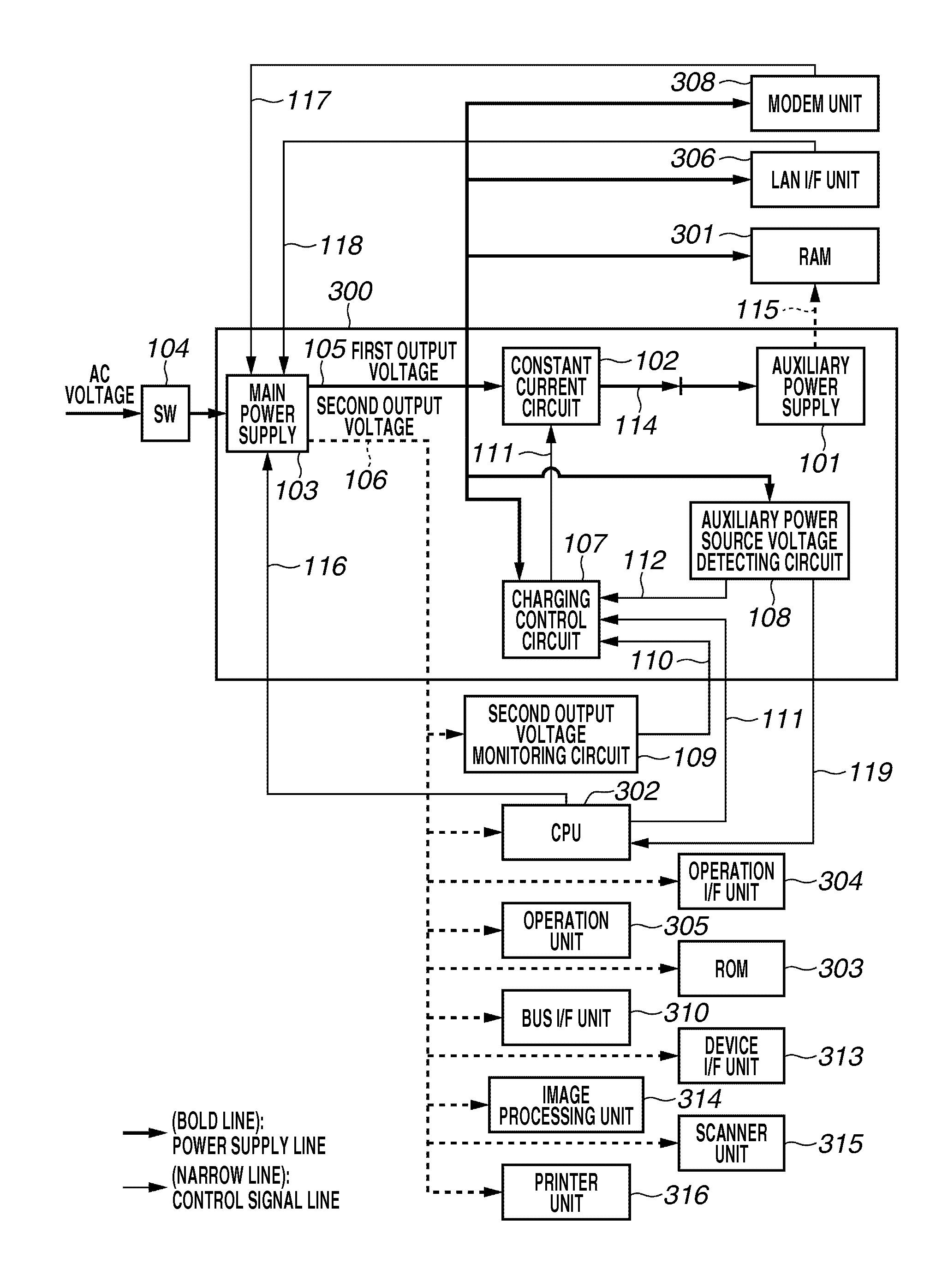
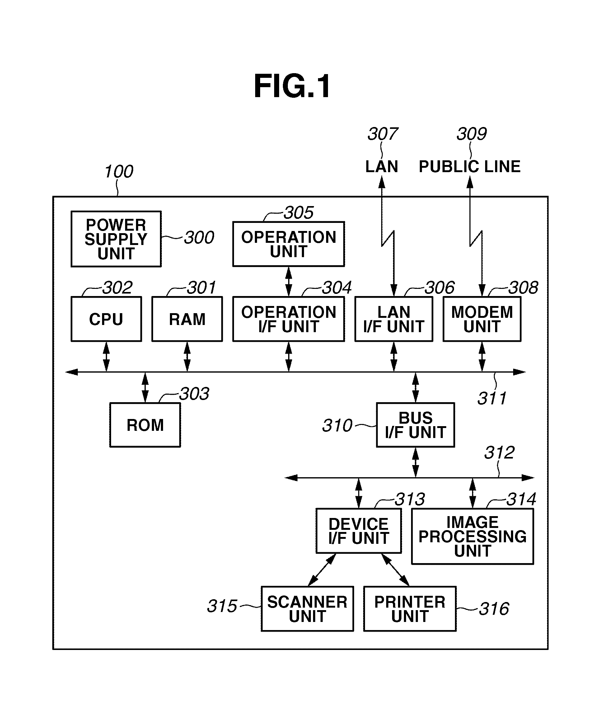
[0024]FIG. 1 is a block diagram for illustrating a hardware configuration of a printing device according to the first exemplary embodiment of the present invention.

[0025]Referring to FIG. 1, the printing device 100 includes components 300 to 316 as described below.

[0026]A CPU 302 controls each part by transmitting commands to the components 301, 304, 306, and 308 connected to a system bus 311 via the system bus 311. Also, the CPU 302 controls each part 313 and 314 connected to an image bus 312 by transmitting commands to the image bus 312 via a bus interface (I / F) unit 310.

[0027]A random access memory (RAM) 301 as a storage unit stores image data input from a scanner unit 315 ...


PUM


Abstract

A charge control apparatus operable in a first power mode or a second power mode having power consumption less than that of the first power mode, the charge control apparatus includes a main power supply, an auxiliary power supply, a charging unit, a time count unit, and a charge control unit, wherein the charge control unit controls the charging unit to switch from a first charge mode to a second charge mode upon detecting that the charging time counted by the time count unit is or larger than a predetermined time period in the first power mode, and wherein the charge control unit controls the charging unit to operate in the second charge mode when the charge control apparatus operates in the second power mode.

Description

BACKGROUND OF THE INVENTION[0001]1. Field of the Invention[0002]The present invention relates to a charge control apparatus and a method for controlling the same.[0003]2. Description of the Related Art[0004]Conventionally, as a known technology, an auxiliary power supply (such as a secondary power supply or secondary battery) is provided to make a backup of data stored in a volatile memory such as a dynamic random access memory (DRAM) installed in an electronic device in preparation for power-down of the device.[0005]The auxiliary power supply is charged by a main power supply of the electronic device to accumulate electric charges before the main power supply is powered down. Then, the accumulated electric charges are discharged when the device is powered down. Since the auxiliary power supply has only a limited charge capacity, it may be overcharged if the charging is continued beyond its limit (i.e., in a fully charged state). This may cause an adverse effect on lifetime of the a...

Claims


Application Information

Patent Timeline
Patent Type & Authority Patents(United States)
IPC IPC(8): H02J9/00H02J7/04
CPCH02J7/0093H02J7/041Y10T307/615Y10T307/625H02J7/0071H02J7/00711H02J7/04
Inventor UTSUMI, YUICHI
Owner CANON KK
Why Eureka
Try Eureka