Protective apparatus for energy storage device

a technology for energy storage devices and protective apparatuses, applied in secondary cells, safety/protection circuits, instruments, etc., can solve problems such as increasing current consumption, and achieve the effect of reducing current consumption for switching

Active Publication Date: 2021-09-21
GS YUASA INT LTD
View PDF18 Cites 0 Cited by
  • Summary
  • Abstract
  • Description
  • Claims
  • Application Information

AI Technical Summary

Benefits of technology

[0019]On the other hand, in a case where the rectifier device allows current to flow only in the direction of discharging the energy storage device, the energy storage device can be protected from overcharge by switching the on-off switch to the cutoff state when the overcharge is expected. When an electrical load is connected in that state, discharge current is allowed to flow from the energy storage device to the electrical load via the rectifier device, thereby permitting discharge.

Problems solved by technology

However, when the switch is brought into the closed state by the software's control, current consumption may increase.

Method used


Image

  • Protective apparatus for energy storage device
  • Protective apparatus for energy storage device
  • Protective apparatus for energy storage device

Examples


first embodiment

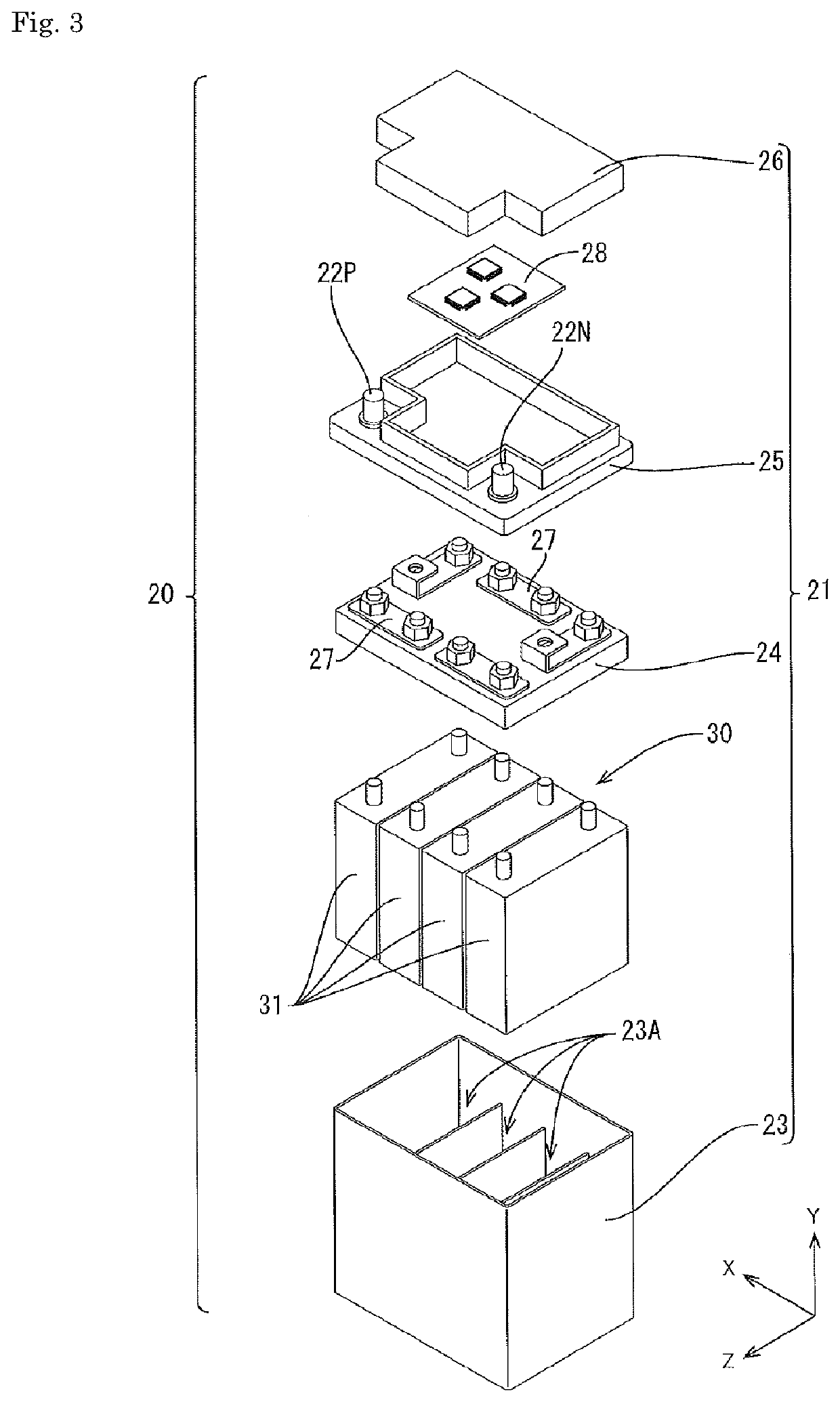
[0031]A first embodiment will be described with reference to FIGS. 1 to 8. In the following description, referring to FIGS. 2 and 3, a vertical direction of a battery case 21 at the time when the battery case 21 is placed horizontally without being inclined with respect to the installation surface is taken as the Y-direction, a direction along the long side of the battery case 21 is taken as the X-direction, and the depth direction of the battery case 21 is taken as the Z-direction.

[0032](1) Structure of Battery

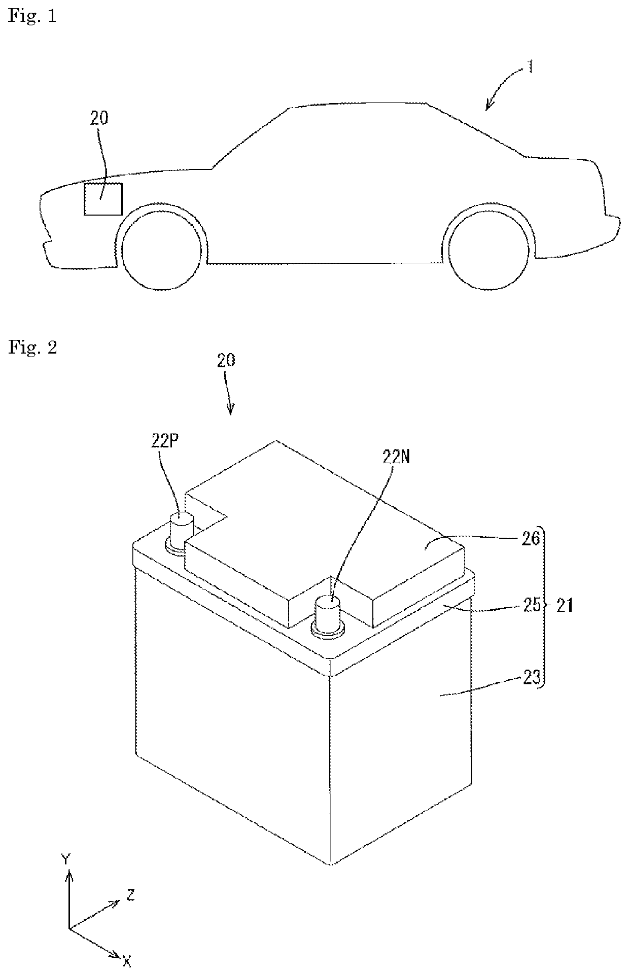
[0033]As shown in FIG. 1, a battery 20 is mounted on an automobile 1 such as an electric car or a hybrid car, and supplies electric power to an electrical load 3 (cf. FIG. 4) such as a power source that operates with electric energy.

[0034]As shown in FIG. 2, the battery 20 has a block-shaped battery case 21. As shown in FIG. 3, the battery case 21 accommodates an assembled battery 30 with a plurality of battery cells 31 connected in series, a control board 28, and the like. T...


PUM

PropertyMeasurementUnit
magnetic fluxaaaaaaaaaa
electric poweraaaaaaaaaa
current consumptionaaaaaaaaaa

Abstract

A battery management system (BMS) is provided, which includes: an on-off switch provided in a current path connecting an assembled battery and electrical equipment; a controller that switches the on-off switch to an off-state when an abnormality in the assembled battery is expected; and a bypass route connected in parallel with the on-off switch and having at least one of a parasitic diode that allows current to flow only in a direction of charging the assembled battery and a parasitic diode that allows current to flow only in a direction of discharging the assembled battery. A second excitation coil is connected in series with the parasitic diode and the parasitic diode 50B in the bypass route, the second excitation coil switching the on-off switch to an on-state with magnetic flux by flow of current with a predetermined current value.

Description

CROSS REFERENCE TO RELATED APPLICATIONS[0001]This application is a national stage application, filed under 35 U.S.C. § 371, of International Application No. PCT / JP2018 / 020446, filed May 29, 2018, which claims priority to Japanese Application No. 2017-110909, filed Jun. 5, 2017, the contents of both of which as are hereby incorporated by reference in their entirety.BACKGROUNDTechnical Field[0002]The present invention relates to a technique for protecting an energy storage device.Description of Related Art[0003]There is known a technique for permitting charge and discharge of an energy storage device while protecting the energy storage device from abnormalities such as overcharge and overdischarge (e.g., see JP-A-2014-217169). An energy storage apparatus described in Patent Document 1 includes a plurality of switches connected in parallel to each other and a rectifier device connected in series to any one switch, which are provided between electrical equipment and an energy storage de...

Claims


Application Information

Patent Timeline
Patent Type & Authority Patents(United States)
IPC IPC(8): H02J7/00H01M10/42
CPCH02J7/00302H01M10/425H02J7/00306H01M2010/4271H01M10/42H02H7/18H02J7/00G01R31/36H02J1/06H02J7/0031H02J2310/48Y02E60/10
Inventor IMANAKA, YUKI
Owner GS YUASA INT LTD
Why Eureka
Try Eureka