Automatic gain control circuit

a gain control circuit and gain control technology, applied in gain control, volume compression/expansion having semiconductor devices, electrical transducers, etc., can solve the problems of increasing the number of parts of the whole audio appliance including the agc circuit, affecting the output signal of the power amplifier, and increasing the cost, so as to improve the time density, shorten the attack time, and increase the time density

Active Publication Date: 2011-11-15
YAMAHA CORP
View PDF27 Cites 1 Cited by
  • Summary
  • Abstract
  • Description
  • Claims
  • Application Information

AI Technical Summary

Benefits of technology

[0005]The prevent invention has been made to solve the above-described problem of the conventional technical ideas, and therefore, has an object to provide an AGC circuit capable of controlling a gain with respect to an input audio signal without distorting an output signal of a power amplifier, and capable of preventing a clip by lowering the gain when there is a risk that the clip may be produced.
[0006]Another object of the present invention is to provide an automatic gain control circuit which can suitably set an attack time and a release time without employing an external time constant circuit.
[0010]In accordance with the present invention, as the means for controlling the gain, not such a non-linear element as VCA is employed, but the electronic volume is employed. As a result, the gain can be controlled without distorting the output signal of the power amplifier with respect to the input audio signal. In the case that the level of the output signal of the electronic volume exceeds the previously set output amplitude upper limit level, a control operation for lowering the gain of the electronic volume is carried out, so that the level of the output signal of the electronic volume is limited within the output amplitude upper limit level. As a consequence, if the output amplitude upper limit level is set to be coincident with an upper limit of an input level at which a clip is not produced in a power amplifier provided at a post stage of the electronic volume, then the gain is reduced where there is such a risk that the clip may occur. As a result, it is possible to prevent the clip in the power amplifier.
[0018]With this arrangement, the automatic gain control circuit is arranged in such a manner that the gain corresponding to the level section to which the level of the input audio signal belongs is set to the electronic volume. In addition, the level section and the gain of the input audio signal are related to each other in such a manner that the level of the output signal of the electronic volume does not exceed the previously set output amplitude upper limit level. As a consequence, the output amplitude upper limit level is set to a proper level by which the clip does not occur in the power amplifier of the post stage, so that it is possible to avoid the occurrence of the clip in the power amplifier of the post stage.
[0019]In this preferred mode, the corresponding relationship between the gain and the level section of the input audio signal is properly determined, not only the above-described clip preventing effect, but also other effects may be achieved. For instance, a gain corresponding to a level section equivalent to a large sound volume area is lowered. As a result, while a dynamic range may be suppressed, the unpleasant large sound volume may be reduced. Alternatively, a gain with respect to a level section equivalent to a small sound volume may be increased in order that small sound may be amplified in an easy listening sound volume.
[0029]With this arrangement, the higher the time density when the first and third controls are performed, the attack time is shorten, and the higher the time density when the second and fourth controls are performed, the release time is shorten. Therefore, by setting appropriately the frequencies of respective values which are the triggers of the respective first to fourth controls, the desired attack time and release time can be obtained.

Problems solved by technology

Although such utilization modes of these AGC circuits have merits to prevent clips, there is such a problem that since non-linear elements such as VCA and the like are used, the output signals of the power amplifiers are distorted.
Therefore, number of parts of the whole audio appliance including the AGC circuit increased, and thereby increasing the cost.
Further, the time constant of the time constant circuit may be sensitive to the temperature and may change over time.
Thus, if this circuit is used or the AGC circuit, the problem arises in which stabilities of the attack time and the release are poor.

Method used


Image

  • Automatic gain control circuit
  • Automatic gain control circuit
  • Automatic gain control circuit

Examples


first embodiment

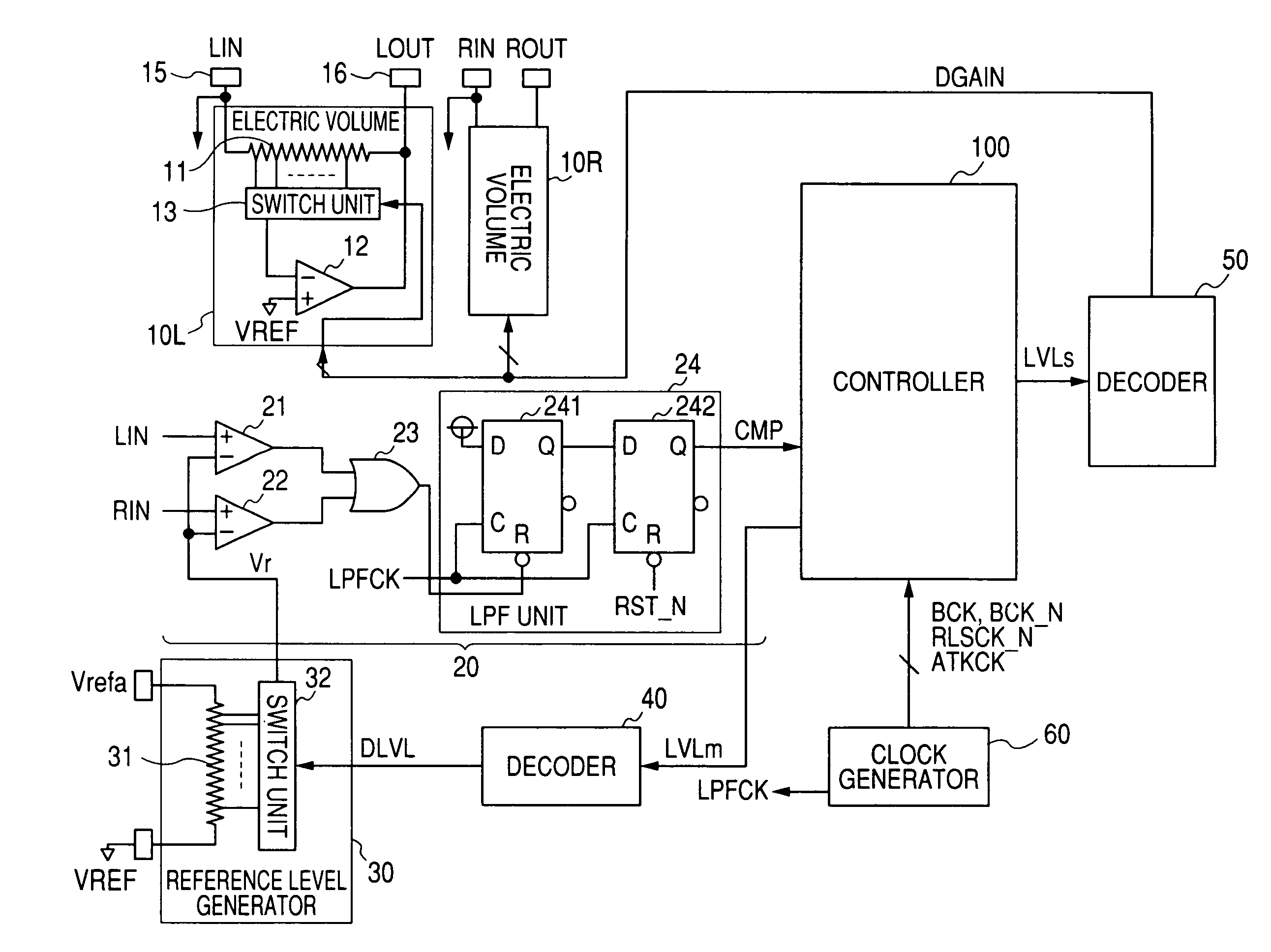
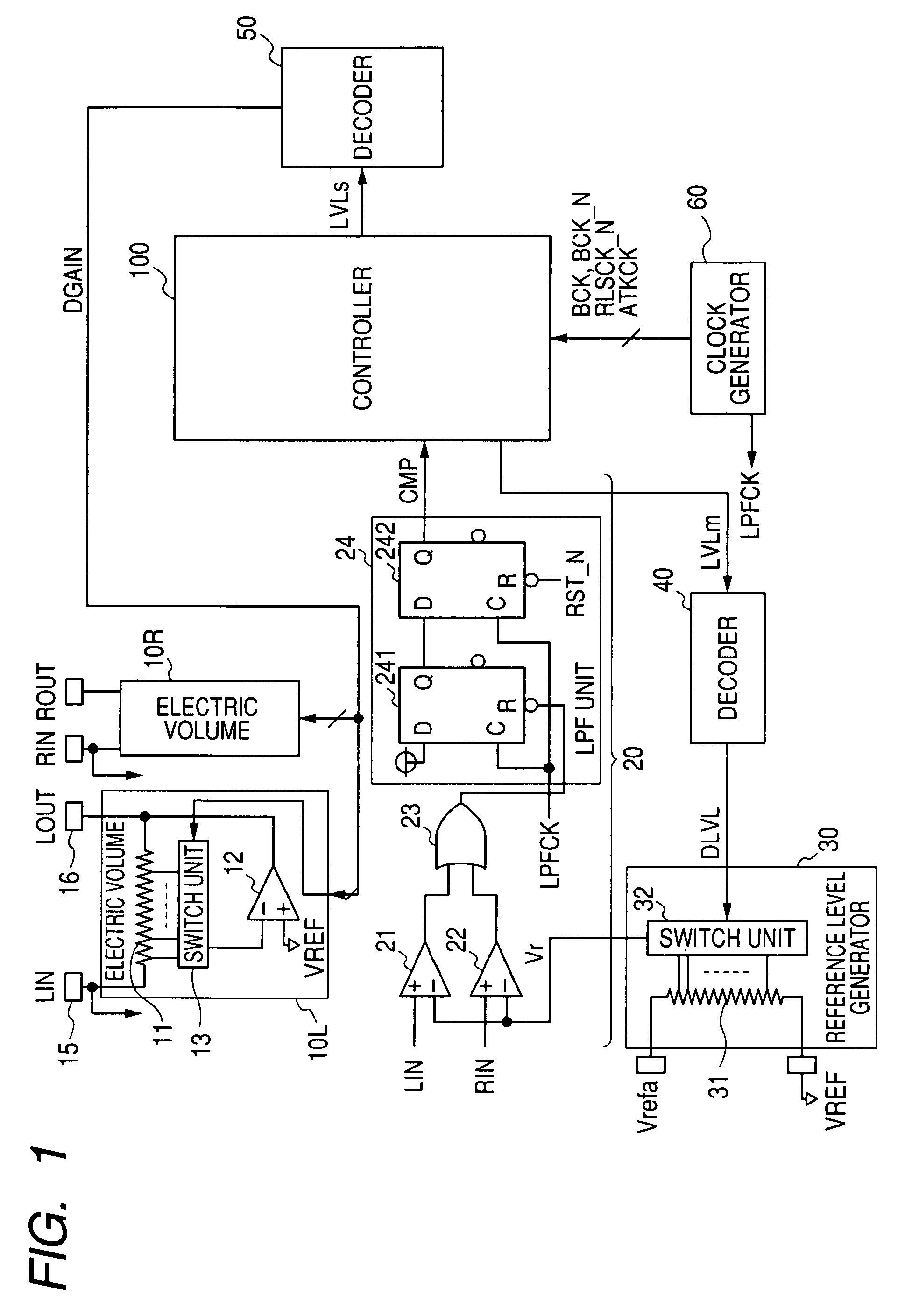
[0042]FIG. 1 is a block diagram for indicating an arrangement of an AGC (automatic gain control) circuit according to a first embodiment of the present invention. The AGC circuit according to the first embodiment is a semiconductor integrated circuit in which electronic volumes 10L and 19R, a level judging unit 20, a reference level generator 30, decoders 40 and 50, a clock generator 60, and a controller 100 are formed on a semiconductor substrate. The AGC circuit is mounted on, for example, an audio appliance such as a speaker reproducing apparatus.

[0043]The electronic volumes 10L and 10R are circuits which amplify an L-channel input audio signal LIN and an R-channel input audio signal RIN based on gains designated by gain designation data DGAIN respectively, and output an audio signal LOUT and another audio signal ROUT. The gain designation data DGAIN are applied from the decoder 50 among “N” sorts of gains G(K) (K=1 to N), while a magnitude relationship is given as G(1)>G(2)>, - ...


PUM


Abstract

A controller 100 updates data LVLm indicative of a level section of an input audio signal and controls a reference level Vr based on a signal CMP representative of a comparison result between the input audio signal and the reference level Vr, and further, controls gains of electronic volumes 10L and 10R in such a manner that these gains become such gains corresponding to the level section of the input audio signal. In this case, the level sections of the input audio signals are related to the gains in such a manner that levels of output signals of the electronic volumes do not exceed a previously set output amplitude upper limit level.

Description

BACKGROUND OF THE INVENTION[0001]The present invention is related to an automatic gain control circuit suitably used to control a gain of an audio appliance.[0002]In general, automatic gain control circuits (will be referred to as “AGC circuits” hereinafter) have been provided at a pre-stage of a power amplifier in output stage of an audio appliance such as speaker reproducing apparatus and recording apparatus. The above-described AGC circuit is a circuit equipped with a function capable of controlling a gain when input audio signals are amplified in order that even under such a condition that peak levels of waveforms of the input audio signals are varied, the input audio signals are amplified in proper levels and then the amplified input audio signals having the proper levels are supplied to a power amplifier. There are some possibilities that this sort of AGC circuits are employed as means for preventing occurrences of clips in power amplifiers employed in output stages of audio a...

Claims


Application Information

Patent Timeline
Patent Type & Authority Patents(United States)
IPC IPC(8): H03G3/00
CPCH03G3/001H03G3/3026H03G7/06H03G3/20
Inventor TANAKA, YASUOMITSUJI, NOBUAKIKAWAI, HIROTAKA
Owner YAMAHA CORP
Why Eureka
Try Eureka