
Heatset annuloplasty suture guide

a suture guide and heatset technology, applied in the field of suture guides, can solve the problems of affecting the installation of annuloplasty rings, the damage to both valves, and the difficulty of repair or replacement of valves, and achieve the effect of sufficient structural integrity and easy attachment of the suture guid

Active Publication Date: 2011-11-01
MEDTRONIC INC
View PDF3 Cites 4 Cited by
  • Summary
  • Abstract
  • Description
  • Claims
  • Application Information

AI Technical Summary

Benefits of technology

[0013]The implantable annuloplasty suture guide of the present invention maintains its basic configuration without the rigidity of the internal frame suture guides such as Carpenter et al. guides. In addition, the said annuloplasty guide has sufficient structural integrity to allow it to be used with a holder providing radially spaced support for the suture guide as opposed to support over the entire circumference of the suture guide. This both makes it easier to attach the suture guide to the holder and allows more access to the suture guide during installation of the suture guide in a heart valve annulus.

Problems solved by technology

Both valves are subject to damage that requires the valves to be repaired or replaced.
Those annuloplasty rings having an internal frame can be difficult to install if there is even slight deviation in patient anatomy in the vicinity of an annulus defined by tissue surrounding a human heart valve.
Thus, this is one limitation on Carpenter et al.
Because flexible annuloplasty rings can be hard for surgeons to manipulate and install due to their flexible nature, flexible rings typically require a holder for installation by a surgeon.
However, fully attaching flexible annuloplasty rings to the circumference of a holder can present difficulties that require relatively tight tolerances between the annuloplasty rings and a holder and the connection process can drive up costs.
In addition, known flexible suture rings require attachment of the entire inner circumferential surface of the annuloplasty ring to the holder, which can make it difficult to view the surgical field in the vicinity of a valve annulus and can inhibit access to all portions of the annuloplasty ring.

Method used


Image

  • Heatset annuloplasty suture guide
  • Heatset annuloplasty suture guide
  • Heatset annuloplasty suture guide

Examples


Embodiment Construction

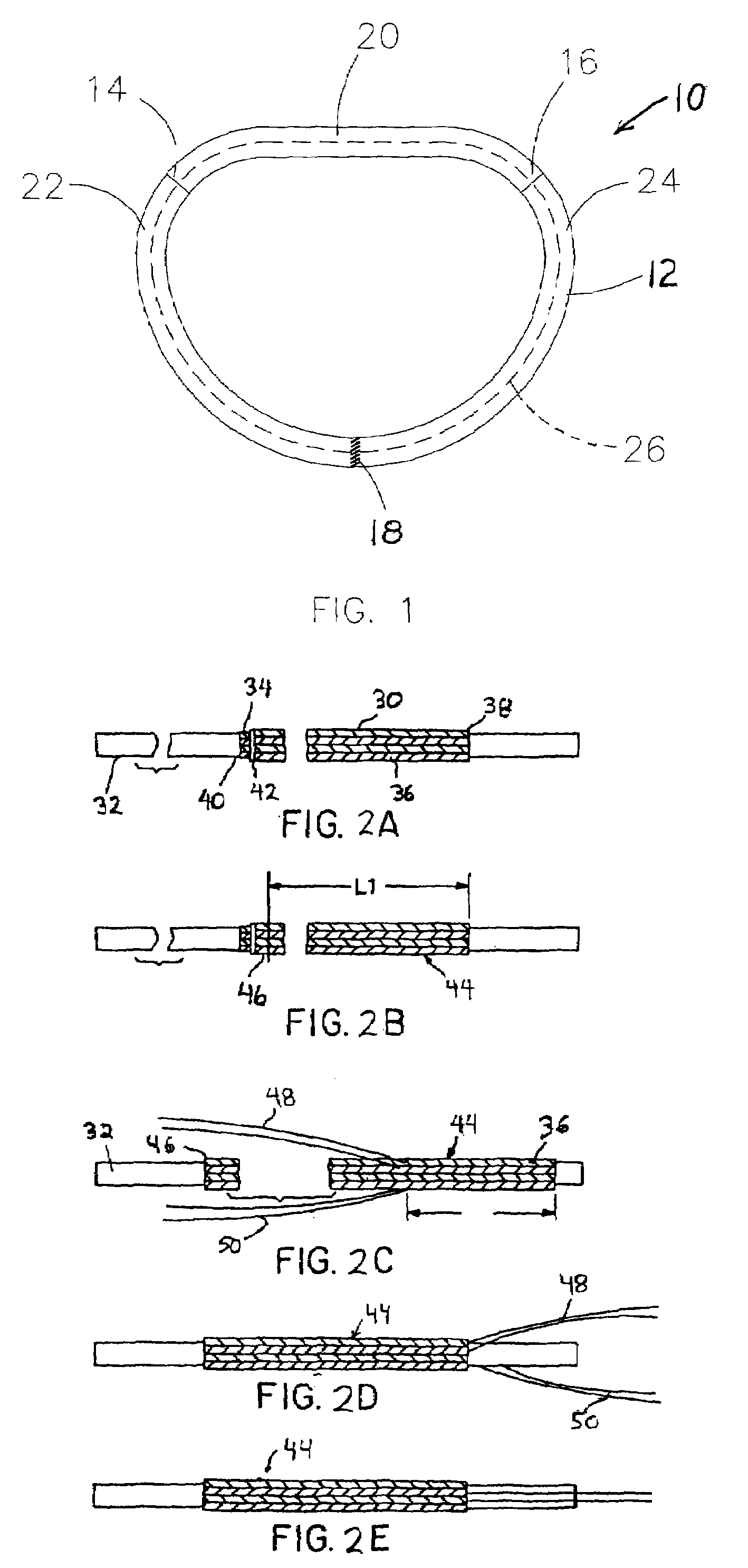
[0034]A D-shaped heatset annuloplasty suture guide 10 for use in valve repair is shown in a plan view in FIG. 1. The D-shaped annuloplasty suture guide 10 consists of a elongate braided ribbon body 12 made of a heat settable material that has been heatset to a curved lengthwise configuration, in this case a D-shape corresponding to an annulus of a mitral valve in a human heart. The D-shaped annuloplasty suture guide includes colored trigon markers 14, 16 corresponding to the left and right fibrous trigon the mitral valve. The elongate braided ribbon body 12 has its ends sewn together at the seam 18 to form a ring. The ring has three segments, an anterior segment 20, a right posterior segment 22 and a left posterior segment 24. In one embodiment, the braided heat setable ribbon body 12 is tubular and a radio opaque marker indicated in ghost lines at 26 resides within the tube.

[0035]The braided heat setable ribbon is made a biocompatible cloth, for example, a tubular braided polyether...


PUM

PropertyMeasurementUnit
lengthaaaaaaaaaa
lengthaaaaaaaaaa
distanceaaaaaaaaaa

Abstract

An implantable annuloplasty suture guide is intended to lie against at least a portion of an annulus surrounding a human heart. The implantable annuloplasty suture guide is made of an elongated ribbon of braided, heat setable material. The braided, heat-setable material is heat-set in a curved lengthwise configuration corresponding to at least a portion of the annulus of the human heart valve. A method of making an implantable annuloplasty suture guide configured to lie against at least a portion of an annulus defined by tissue surrounding a human heart. The method includes the steps of providing an elongate biocompatible ribbon comprising a braided, heat setable material. A fixture is provided, with the fixture comprising a heat conducting material defining an elongate cavity having a curved length-wise configuration corresponding to at least a portion of the annulus defined by the tissue surrounding the human heart. The elongate biocompatible ribbon is placed in the cavity and the fixture is heated to provide a select temperature for a select time in the cavity, the select temperature and the select time being sufficient to heat-set the elongate biocompatible ribbon in the curved length-wise configuration.

Description

RELATED APPLICATIONS[0001]This application claims priority from U.S. Provisional Patent Application Ser. No. 60 / 763,005, filed Jan. 27, 2006, entitled “Heatset Annuloplasty Suture Guide,” which is hereby incorporated by reference.TECHNICAL FIELD[0002]The present invention is directed toward suture guides, and more particularly toward heatset annuloplasty suture guides and a method of making the same.BACKGROUND OF THE INVENTION[0003]It is well known in the art to use implantable annuloplasty suture guides for surgical correction of certain mitral or tricuspid heart valve disorders. The heart has two atrio-ventricular valves. The mitral valve is on the left side of the heart and the tricuspid valve is on the right side of the heart. Both valves are subject to damage that requires the valves to be repaired or replaced. Clinical experience has shown that repair of the valve, where this technique is possible, produces better long term results than does valve replacement. The mitral and t...

Claims


Application Information

Patent Timeline
Patent Type & Authority Patents(United States)
IPC IPC(8): B29C65/00
CPCA61F2/2445A61F2/2448
Inventor WRIGHT, JOHN T. M.
Owner MEDTRONIC INC
Learn More