
Evaporation supply apparatus for raw material and automatic pressure regulating device used therewith

a technology of automatic pressure regulation and evaporation supply, which is applied in the direction of fluid pressure control, chemical vapor deposition coating, gas purification by liquid washing, etc., can solve the problem of significant difficulty in highly accurate control of the mixture ratio between gases, lack of consistency, and difficulty in highly accurate control of the supply amount of mixed gas g/sub>0 /sub>, etc. problem, to achieve the effect of promoting evaporation of raw materials, high accuracy

Inactive Publication Date: 2011-11-01
FUJIKIN INC
View PDF19 Cites 15 Cited by
  • Summary
  • Abstract
  • Description
  • Claims
  • Application Information

AI Technical Summary

Benefits of technology

The present invention solves the problem of simultaneously achieving parallel downsizing of the evaporation supply apparatus, an increase in the amount of raw material supplied, highly refined accuracy control of the mixture ratio of the raw material and the amount of mixed gas supplied, and inner pressure fluctuation control of the source tank. The invention achieves these goals by using a high-temperature countermeasure to the process chamber mixed gas system, an automatic pressure regulating device, a constant-temperature heating unit, an automatic pressure regulating device, a piezoelectric-element-driven metal diaphragm valve, and a diaphragm retaining member. The invention also includes a source tank in which a raw material is pooled, a flow rate control device, a primary piping path for feeding mixed gas, an automatic pressure regulating device, a constant-temperature heating unit, and an arithmetic control unit for performing the temperature correction of the detected pressure.

Problems solved by technology

However, it proves difficult to highly accurately control the mixture ratio between gases G1 and G4 or the supply flow rate of the mixed gas G0.
As a result, variation may easily occur in film thickness or film composition, and thus, the properties of the manufactured semiconductor are not stabilized, which results in the drawback of a lack of consistency.
As a result, the highly accurate control of the supply amount of the mixed gas G0 is significantly difficult.
Thus, the evaporation supply apparatus is complicated and large, and obtaining a uniform mixture of carrier gas G1 and vapor G4 in the mixture unit 18 is difficult.

Method used


Image

  • Evaporation supply apparatus for raw material and automatic pressure regulating device used therewith
  • Evaporation supply apparatus for raw material and automatic pressure regulating device used therewith
  • Evaporation supply apparatus for raw material and automatic pressure regulating device used therewith

Examples


Embodiment Construction

[0090]Embodiments of the present invention will now be described with reference to the figures.

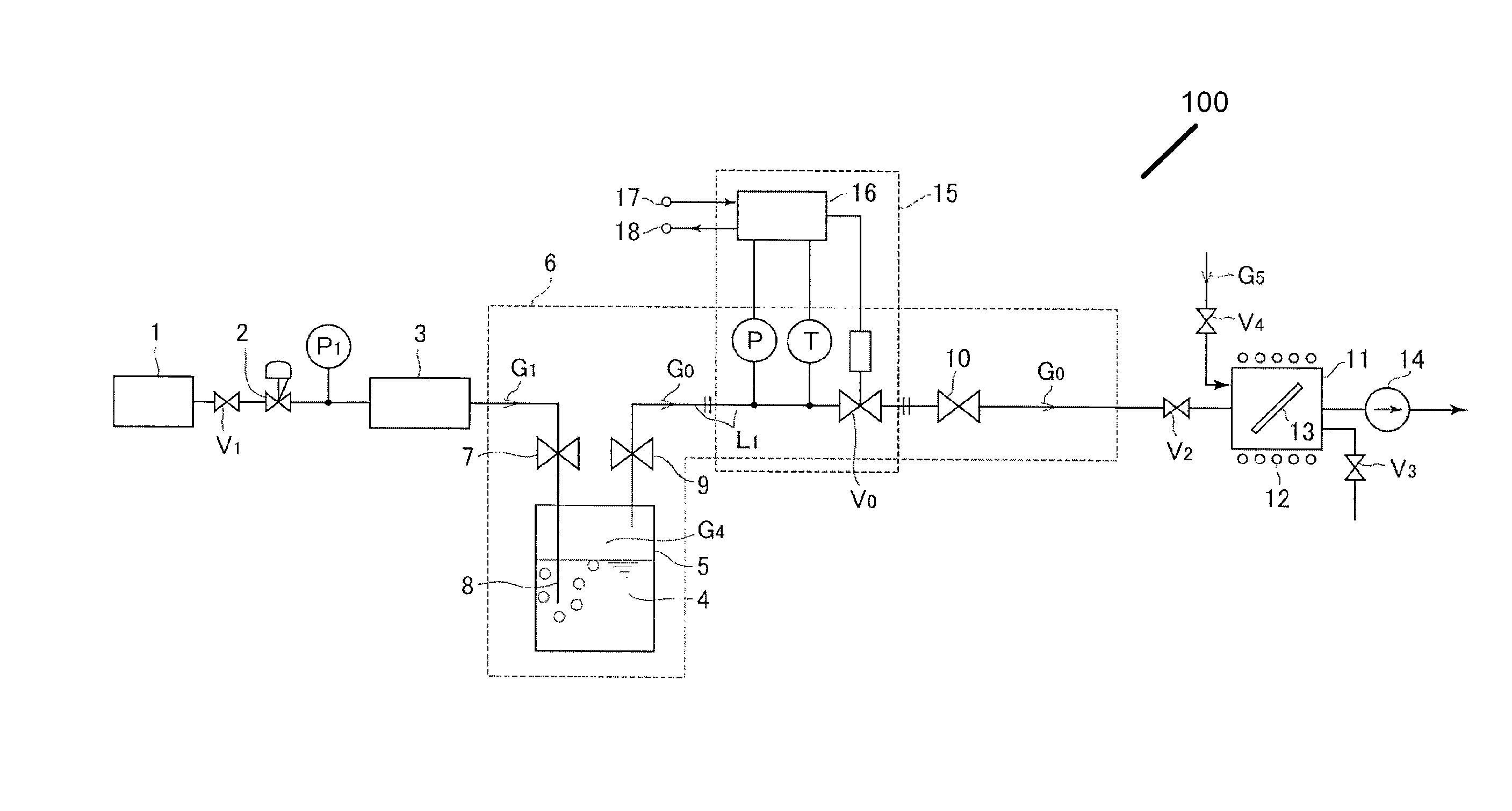
[0091]FIG. 1 is a schematic diagram showing the main components of the evaporation supply apparatus for a raw material according to the present invention. In FIG. 1, reference numeral 1 designates a carrier gas supply source; 2 designates a decompressor; 3 designates a mass flow control device; 4 designates a raw material (liquid raw material such as Al (CH3)3 or supported sublimation solid raw material such as Pb(dpm)2); 5 designates a source tank; 6 designates a high-temperature heating unit; 7, 9, and 10 designate valves; 8 designates a lead-in tube; 11 designates a process chamber, 14 designates a vacuum pump; 15 designates an automatic pressure regulating device in the source tank; 16 designates an arithmetic control unit; 17 designates an input terminal of a set pressure signal; 18 designates an output terminal of a detected pressure signal; G1 refers to a carrier gas such as H2; G4 ...


PUM

PropertyMeasurementUnit
temperatureaaaaaaaaaa
pressureaaaaaaaaaa
operating temperatureaaaaaaaaaa

Abstract

An evaporation supply apparatus for raw material used in semiconductor manufacturing includes a source tank in which a raw material is pooled; a flow rate control device that supplies carrier gas at a regulated flow rate into the source tank; a primary piping path for feeding mixed gas G0, made up of raw material vapor G4 and carrier gas G1, an automatic pressure regulating device that regulates a control valve based on the detected values of the pressure and temperature of mixed gas G0 to regulate the cross-sectional area of the passage through which the mixed gas G0 is distributed so as to hold the pressure of the mixed gas G0 inside the source tank constant; and a constant-temperature heating unit for heating the source tank to a set temperature, in which mixed gas G0 is supplied to a process chamber while controlling the pressure inside the source tank.

Description

[0001]This is a National Phase Application in the United States of International Patent Application No. PCT / JP2007 / 000628 filed Jun. 13, 2007, which claims priority on Japanese Patent Application No. 2006-177113, filed Jun. 27, 2006. The entire disclosures of the above patent applications are hereby incorporated by reference.FIELD OF THE INVENTION[0002]The present invention relates to an evaporation supply apparatus for the raw material used in a semiconductor manufacturing apparatus configured to form a thin film on a substrate by a so-called metal organic chemical vapor deposition method (hereinafter referred to as “MOCVD method”). In particular, the present invention relates to an evaporation supply apparatus for a raw material, in which the pressure inside a source tank is controlled with high accuracy so as to supply the process chamber with mixed gas having a mixture ratio of raw material vapor to carrier gas that is constant and a flow rate that is exactly controlled to a set...

Claims


Application Information

Patent Timeline
Patent Type & Authority Patents(United States)
IPC IPC(8): B01F3/04
CPCC23C16/4481C23C16/52G05D16/2013G05D16/024Y10T137/7737C23C16/455
Inventor HIRATA, KAORUNAGASE, MASAAKIHIDAKA, ATSUSHIMATSUMOTO, ATSUSHIDOHI, RYOUSUKENISHINO, KOUJIIKEDA, NOBUKAZU
Owner FUJIKIN INC
Learn More