
Thermal cycling device

Active Publication Date: 2011-10-25
THERMAL GRADIENT
View PDF45 Cites 2 Cited by
  • Summary
  • Abstract
  • Description
  • Claims
  • Application Information

AI Technical Summary

Benefits of technology

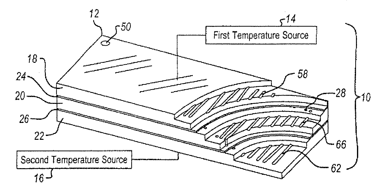
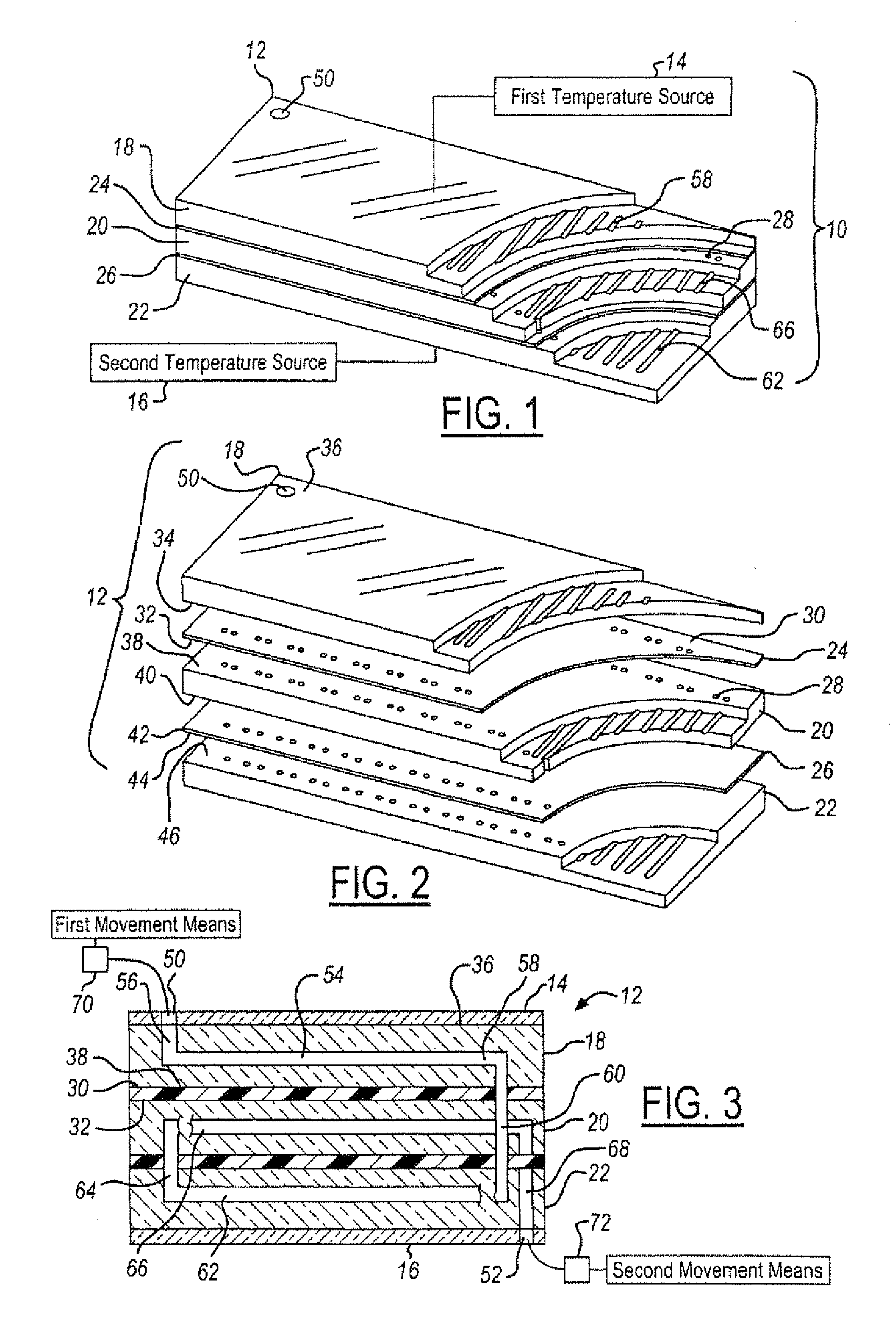
One advantage of the invention is that only two sources of thermal energy are required to perform a polymerase chain reaction that uses three different temperatures. Advantageously, because the upper and lower layers are maintained at a temperature, delays due to thermal cycling of the individual layers are not present. This accelerates the entire process compared to the existing art.

Problems solved by technology

The costs and time associated with the performance of PCR can become prohibitive for scientific studies that require thousands or even millions of PCR reactions.
This results in a slow thermal transition of the sample as it moves through the device.
It also requires that the device be larger and therefore does not provide the highest degree of miniaturization.
Thus, the full cost benefit from reduced PCR sample volumes is not realized.
The time required to perform the thermal cycling is largely determined by thermal mass and other physical properties of the heating device and is therefore relatively slow.
This creates an environment for the undesirable evaporation of the sample.
The covers reduce evaporation but present an opportunity for undesirable condensation.
This effect is often mitigated by heating the cover but this then introduces a competing temperature source to the system, further increasing the total PCR reaction time.
Although these systems are an improvement over the previously described approach, the thermal characteristics of such a structure is a limiting factor.
Also, fabricating, controlling, and monitoring of the in situ heating elements is complicated and adds appreciably to the cost of the device.
However, the total PCR reaction time is still limited by the ability to change temperature within the heating / elements and within the microchannel material.
All of these methods and devices are limited by their ability to transfer thermal energy through the device and into the sample.
Further limitations are present when the heating elements themselves must also change temperature in order to expose the PCR sample to each desired temperature set point in the PCR protocol.

Method used


Image

  • Thermal cycling device
  • Thermal cycling device
  • Thermal cycling device

Examples


second embodiment

A method for operating the present invention includes introducing a sample into the device having a plurality of layers. Prior to the introduction of a sample, the temperatures of the individual layers maintain three temperatures required in the PCR protocol. In this embodiment, the temperature of the bottom thermally conductive layer is lower than the upper thermally conductive layer. Thus, once a steady state has been reached by the three conductive layers the sample is introduced into the device. It should be noted that when thermal equilibrium, the entire upper layer is at the same temperature as the temperature source and the entire lower layer is at the temperature of the lower temperature source. Thus, the device is in equilibrium. The middle layer is at an equilibrium temperature between the upper and lower temperatures. The sample is placed through the input port and in the case of the second embodiment, is provided to an initial denaturing stage longer than the other denat...

sixth embodiment

Referring now to FIG. 16, the present invention is illustrated. In this embodiment, a third temperature source 200 is illustrated. The third temperature source 200 includes a first contact 202 and a second contact 204. The contacts may be configured in a similar manner to that described above with respect to FIG. 11. That is, joule heating may be performed through the device and through the second layer 20v. That is, the extension layer may also be heated. In this embodiment, the insulating layers 24v and 26v may have increased insulating properties so that each of the layers are or are nearly thermally independent. That is, in an embodiment with three temperature sources it may be desirable to reduce or eliminate the thermal dependency of each of the layers. Of course, the heating may also be performed by an independent heating layer such as a polysilicon heater illustrated above. That is, an independent heater such as a polysilicon heater would be located between one or both of th...


PUM

PropertyMeasurementUnit
Temperatureaaaaaaaaaa
Electrical conductoraaaaaaaaaa
aaaaaaaaaa

Abstract

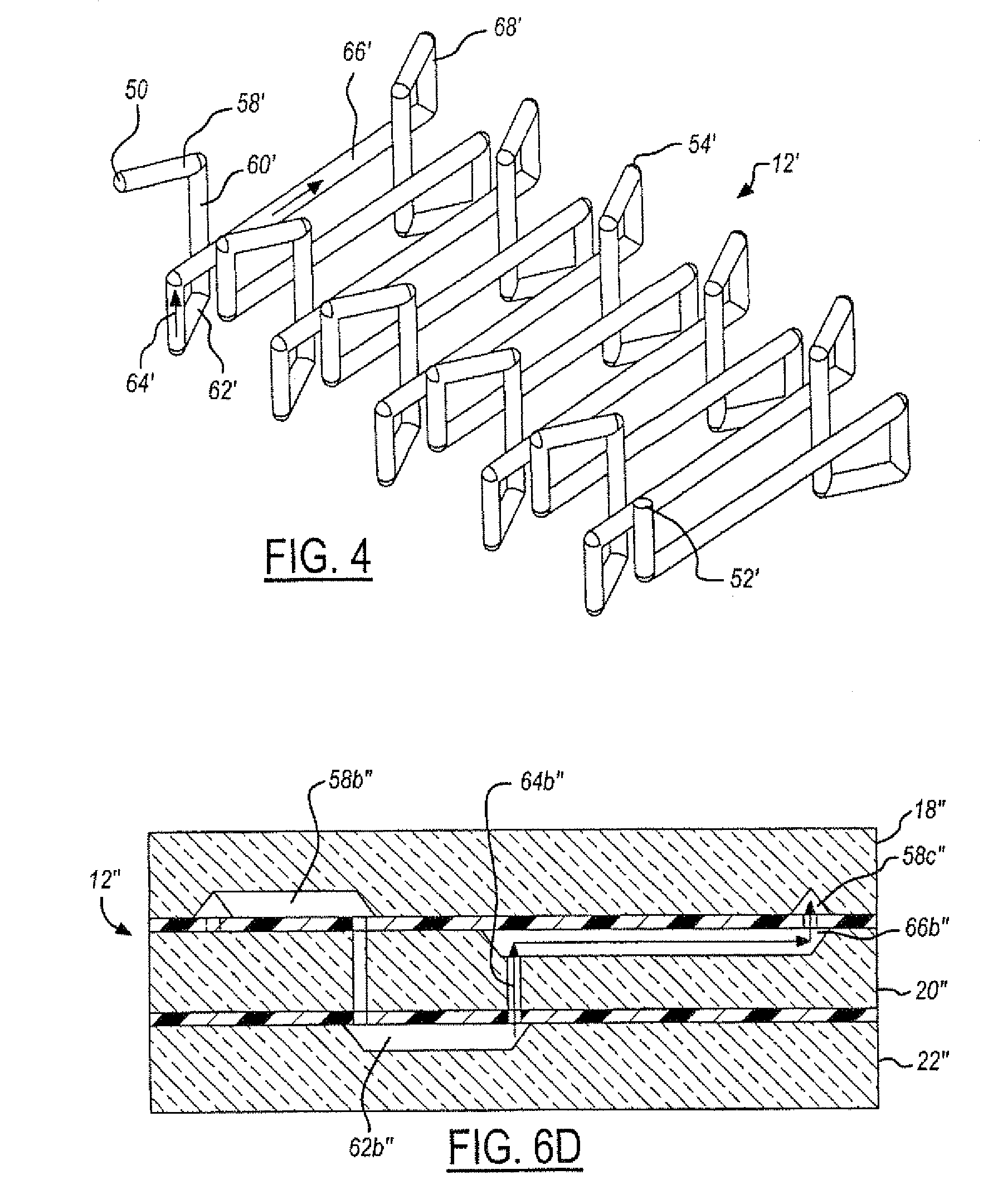
Multi-layer devices suitable for thermal cycling processes. The devices are particularly suitable for performing polymerase chain reactions (PCR). One embodiment includes a first conducting layer, a second conducting layer adjacent to the first layer, and a third conducting layer adjacent to the second layer opposite the first layer. Insulating layers are positioned between said three conducting layers. Continuous channels are formed within the layers. The channels can be formed in either the conducting layer or the insulating layers, or both. Other embodiments include two conducting layers. At least one integral or separate temperature source may be provided to maintain the conducting layers at various desired temperatures.

Description

TECHNICAL FIELDThe present invention relates generally to a thermal cycling devices, and more specifically, to a multi-layer thermal cycling devices suitable for the life science, medical devices and biotechnology fields. One suitable application is to perform a polymerase chain reaction (PCR).BACKGROUNDVarious fields such as life science, medical devices and biotechnology often require thermal cycling for performing various reactions. One type of reaction is the polymerase chain reaction (PCR) in which a biological sample such as a DNA fragment is replicated.PCR has been the preferred method for replicating, or “amplifying” specific and singular nucleic acid constituents in an otherwise complex sample. Among the requirements of the PCR protocol is that the PCR sample, consisting of the biologic sample and PCR reagents, be exposed to three distinct temperatures for a specific length of time. The temperature and time of the exposure is optimized for the particular nucleic acid sequen...

Claims


Application Information

Patent Timeline
IPC IPC(8): C12M1/34C12M3/00C12M1/00C12M1/22
CPCB01L3/5027B01L3/502707B01L7/525C12P19/34B01L2300/0816B01L2300/0874B01L2300/0887B01L2300/1805B01L2300/1883B01L2400/0487
Inventor GROVER, JOEL W.
Owner THERMAL GRADIENT
Learn More