
Wind turbine

a wind turbine and turbine technology, applied in the field of turbines, can solve the problems of reducing the operating efficiency and annual generation time of the wind turbine, unable to utilize the slow moving output airflow to fully derive kinetic energy therefrom, and transferring a relatively low amount of energy, so as to achieve the effect of improving power generation efficiency and slow outpu

Inactive Publication Date: 2011-10-18
LIN CHENG TE
View PDF8 Cites 2 Cited by
  • Summary
  • Abstract
  • Description
  • Claims
  • Application Information

AI Technical Summary

Benefits of technology

"The invention is a wind turbine that improves power generation efficiency by transferring slow output airflow. It includes a housing, multiple cross-flow fan assemblies, a turbine generator assembly, an air guide, and multiple wind-driven fans. The cross-flow fan blades rotate to pull airflow through the chamber, while the turbine generator assembly produces electricity from the airflow. The air guide guides airflow outwards, and the wind-driven fans are driven by the outward airflow, resulting in improved energy extraction efficiency."

Problems solved by technology

However, the conventional wind power generators cannot utilize slow moving output airflow to fully derive kinetic energy therefrom.
Therefore, during relative light wind, the wind turbine may not turn, or may turn too slowly to generate power and during high relative wind speeds, the airflow passes the wind turbine, but only transfers a relatively low amount of energy.
Therefore, operating efficiency and annual generation time of the wind turbine is reduced.

Method used


Image

  • Wind turbine
  • Wind turbine
  • Wind turbine

Examples


Embodiment Construction

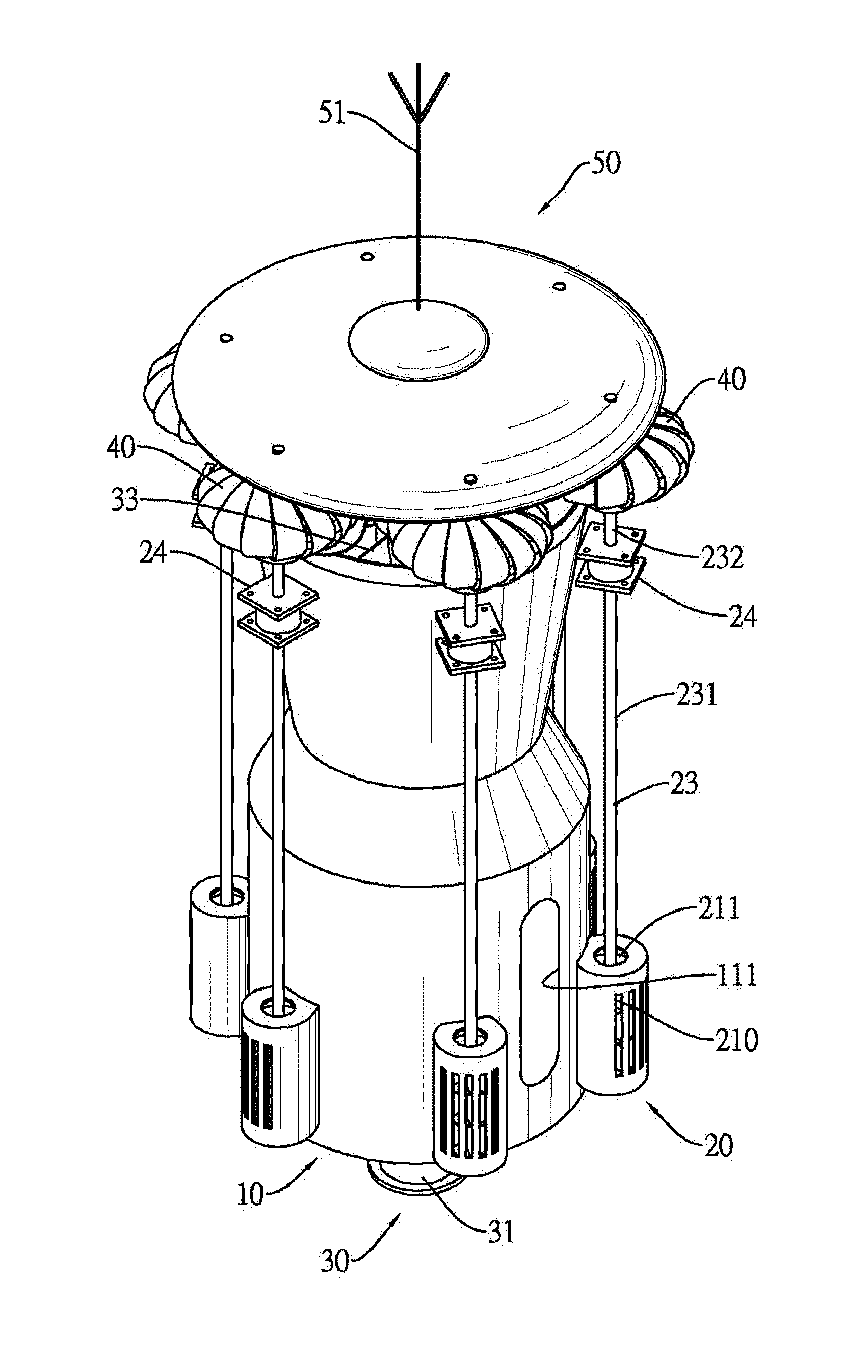
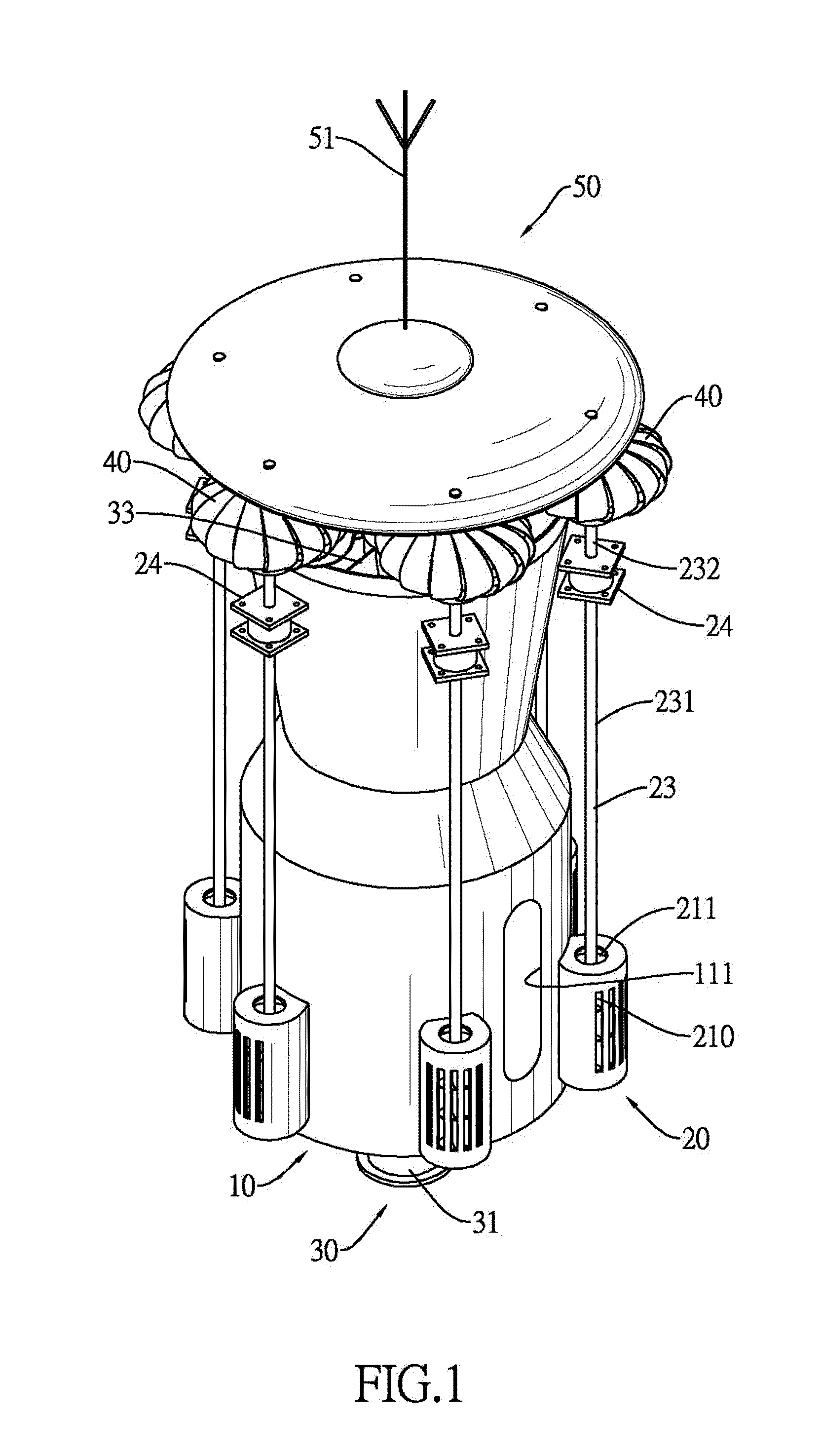
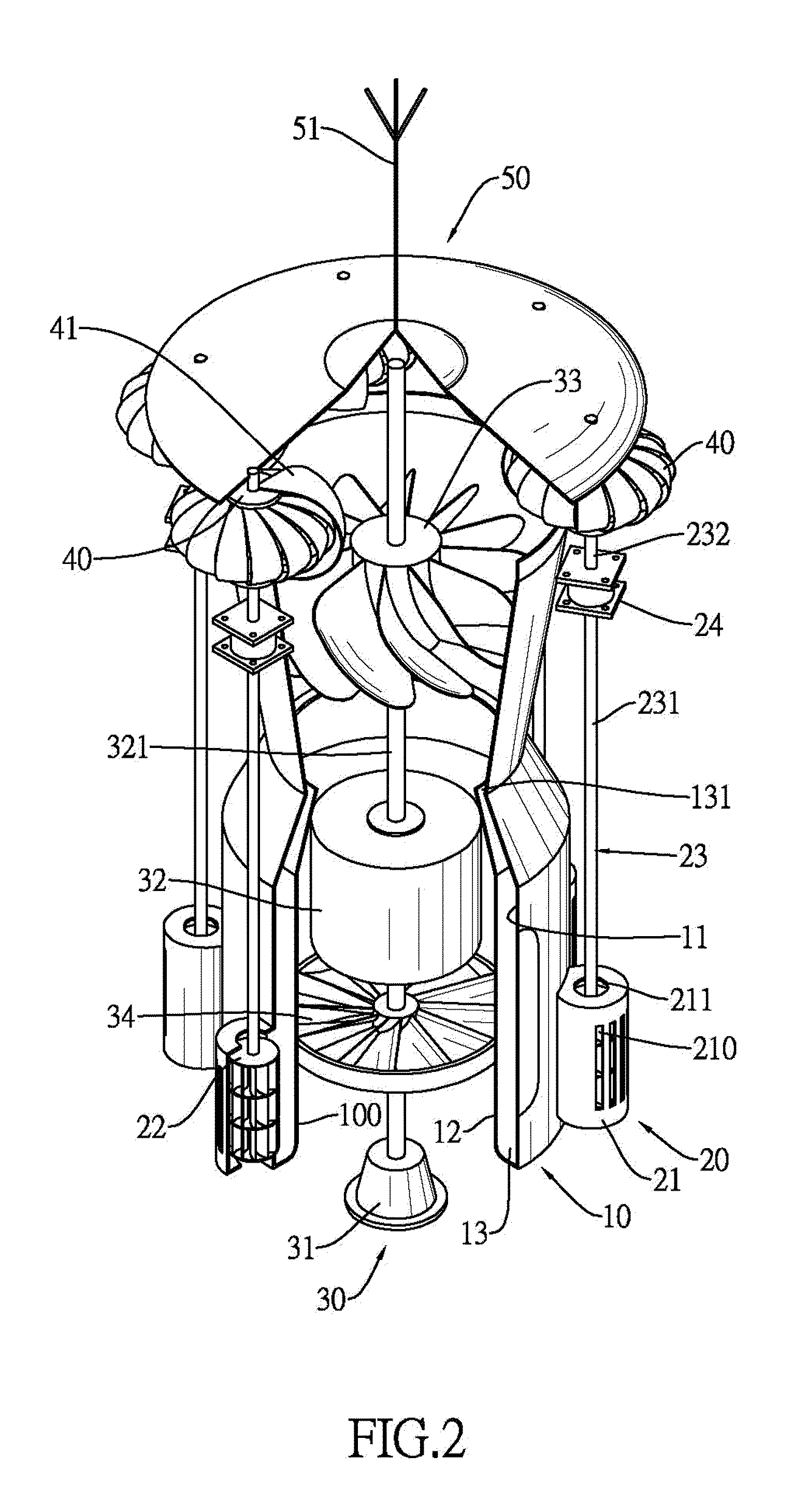
[0021]With reference to FIGS. 1 to 3, a wind turbine in accordance with the present invention comprises a housing (10), multiple cross-flow fan assemblies (20), a turbine generator assembly (30), an air guide (50) and multiple wind-driven fans (40).

[0022]With further reference to FIG. 4, the housing (10) has a chamber (100) and may further have an inner sidewall (12), an outer sidewall (11), a channel (13) and an entrance (111).

[0023]The chamber (100) is defined in the housing (10) and has a top opening and a bottom opening.

[0024]The inner sidewall (12) is annular, is formed on the housing (10) and surrounds the chamber (100).

[0025]The outer sidewall (11) is annular, is formed on the housing (10), surrounds the inner sidewall (12) and may be higher than the inner sidewall (12).

[0026]The channel (13) is annular, is defined between the inner sidewall (12) and the outer sidewall (11) and communicates with the chamber (100).

[0027]The entrance (111) is defined through the inner and outer...


PUM


Abstract

A wind turbine has a housing, multiple cross-flow fan assemblies, a turbine generator assembly, an air guide and multiple wind-driven fans. The housing has a chamber having top and bottom openings. The cross-flow fan assemblies are mounted on the housing and each has a casing, a cross-flow fan blade and a transmission shaft. The cross-fan blade rotates to provide airflow to the chamber. The turbine generator assembly is mounted in the chamber and has a generator, a generator shaft mounted on the generator and a turbine blade mounted on the generator shaft and driven by the airflow to activate the generator. The air guide is mounted on the transmission shafts and guides airflow outwards. The wind-driven fans are mounted respectively on the transmission shafts and are driven by outward airflow. The wind turbine derives energy from the airflow exiting out of the wind turbine for improved energy extraction efficiency.

Description

BACKGROUND OF THE INVENTION[0001]1. Field of the Invention[0002]The present invention relates to a turbine, and more particularly to a wind turbine that transfers external airflow to improve power generating efficiency.[0003]2. Description of Related Art[0004]Conventional wind power generators such as windmills and wind turbines have a generator and rotor. The rotor is connected to the generator and has cross-flow fan blades so that airflow over the cross-flow fan blades rotates the rotor and drives the generator.[0005]However, the conventional wind power generators cannot utilize slow moving output airflow to fully derive kinetic energy therefrom.[0006]However, conventional wind turbines are customized to remove a percentage of energy from the airflow according to average annual wind speeds. Therefore, during relative light wind, the wind turbine may not turn, or may turn too slowly to generate power and during high relative wind speeds, the airflow passes the wind turbine, but onl...

Claims


Application Information

Patent Timeline
Patent Type & Authority Patents(United States)
IPC IPC(8): F03D9/00
CPCF03D3/02F03D3/04F05B2240/132F05B2240/40Y02E10/74F03D9/25
Inventor LIN, CHENG-TE
Owner LIN CHENG TE
Learn More